Operating principle
In terms of working principles, the NutriJet has two variants:
• NutriJet Inline: the unit is installed between the supply line and the main irrigation line, so that
all the irrigation water flows through the unit
• NutriJet Bypass: the unit is installed next to the main line. Part of the water is guided out of the
main line, via the unit, back to the main line. The unit delivers such a high dosage that the correct
dosage is achieved after mixing in the main line.
NutriJet Inline
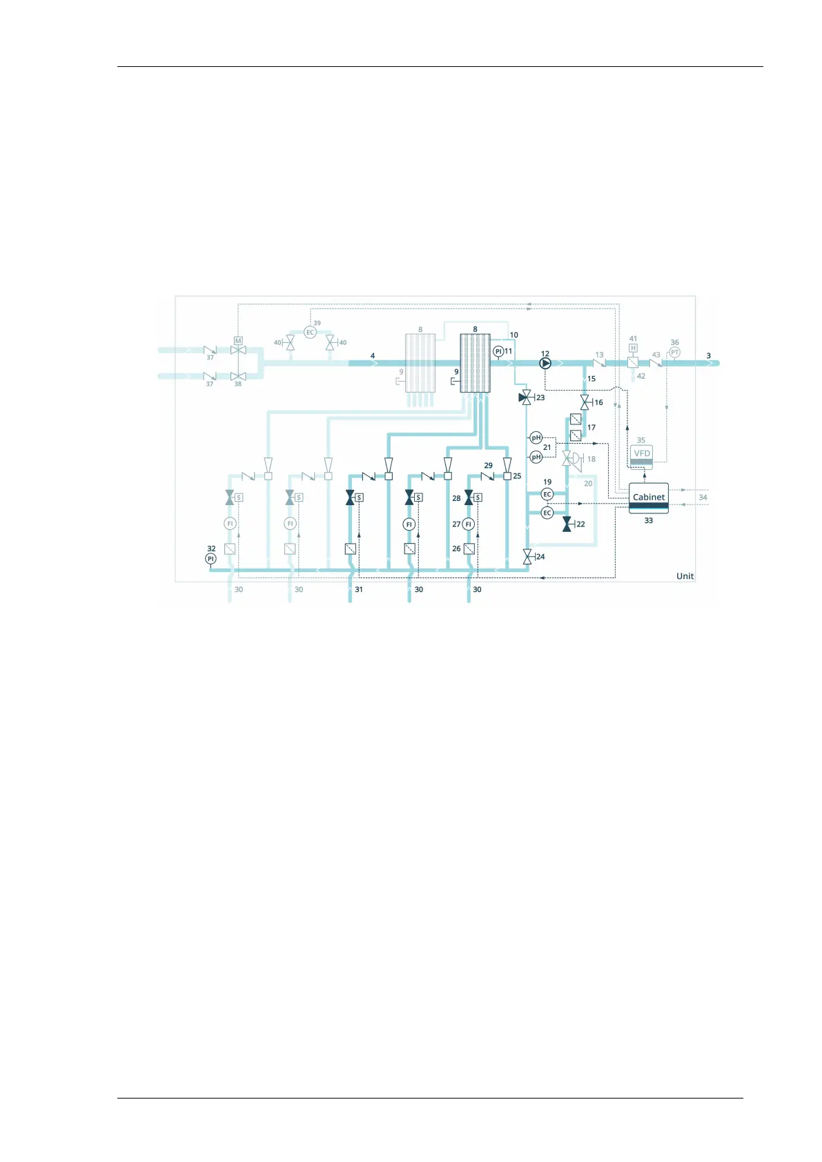
Graphic of NutriJet Inline fertiliser dosing unit
Not all components are supplied as standard. The components that are shown as transparent depend on the
configuration.
The electrical cables are drawn with a dotted line.
Mixing chamber
The system pump (12) suctions the water out of the supply line (4) through the mixing chamber (8)
and pumps it via a non-return valve (13) to the crop (3). Some of the pumped water goes to the
branch (15). The water in the branch flows back into the mixing chamber via the dosing channels.
A mixing chamber has five connections for dosing channels. With an optional second mixing chamber
in series, a maximum of ten connections in total is therefore possible. Not all of the connections
have to be used.
To degas the mixing chamber, a degas line (10) has been made in the mixing chamber. Through the
drain point (9) the mixing chamber can be emptied. A visual check of the suction pressure can be
done by means of the pressure gauge (12) after the mixing chamber.
Dosing channels
The inline dirt filters (17) in the branch prevent clogging of the venturi nozzles in the dosing channels.
The optional pressure reducing valve (18) reduces the pressure of the water to the dosing channels.
A visual check of the pressure of the supply water upstream of the venturi is carried out using the
manometer (32). The nozzles in the venturi (25) create a vacuum that draws in the fertilisers (30)
and acid or lye (31).
NutriJet - user - 00.00216
Priva