13
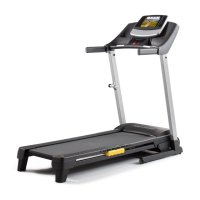
26. Wrap the Ab Cable (47) around a 3 1/2” Pulley (24).
Insert the Ab Cable down through the Press Top
Frame (9). Slide a 3/8” Flat Washer (48) and a 5/8”
x 3/4” Bushing (66) onto a 3/8” x 3 1/4” Bolt (62).
Slide the Bolt through the Press Top Frame and the
3 1/2” Pulley. Secure another 5/8” x 3/4” Bushing
and 3/8” Flat Washer to the Bolt with a 3/8” Nylon
Locknut (50).
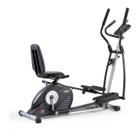
27. Remove the preassembled 3/8” x 2” Bolts (54) from
the other Adjustable Pulley Plates (23).
Wrap the Ab Cable (47) around a 3 1/2” Pulley (24).
Attach the 3 1/2” Pulley and a Cable Trap (25)
between the top holes in the Adjustable Pulley
Plates (23) with a 3/8” x 2” Bolt (54) and a 3/8”
Nylon Locknut (50). Be sure that the Cable Trap
is turned to hold the Cable in place.
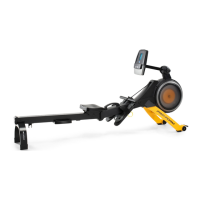
28. Wrap the Ab Cable (47) around a 3 1/2” Pulley (24).
Attach the 3 1/2” Pulley to the rear bracket on the
Press Top Frame (9) with a 3/8” x 2” Bolt (54) and a
3/8” Nylon Locknut (50). Be sure the Ab Cable is
routed in the direction shown.
Wrap the Ab Cable (47) around another 3 1/2”
Pulley (24). Attach the 3 1/2” Pulley to the forward
bracket on the Press Top Frame (9) with a 3/8” x 2”
Bolt (54) and a 3/8” Nylon Locknut (50).
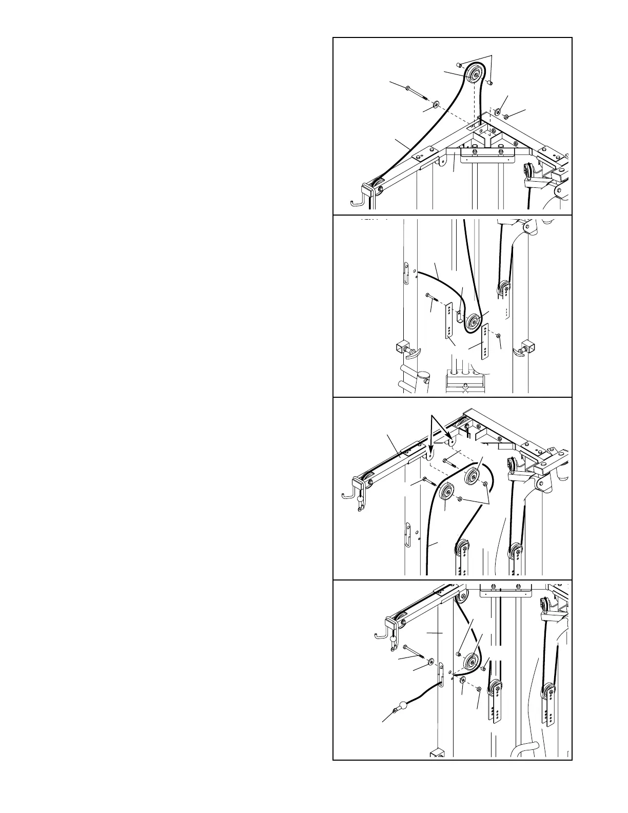
29. Wrap the Ab Cable (47) around a 4 1/2” Pulley (82)
and slide the Ab Cable through the hole in the
Press Upright (2). Slide a 3/8” Flat Washer (48) and
a 5/8” x 1” Bushing (103) onto a 3/8” x 3 3/4” Bolt
(102). Slide the Bolt through the Press Upright and
the 4 1/2” Pulley. Secure another 5/8” x 1” Bushing
and 3/8” Flat Washer to the Bolt with a 3/8” Nylon
Locknut (50).
29
26
27
28
66
48
50
48
62
24
47
9
47
23
54
82
50
9
Bracket
48
2
24
47
24
54
54
50
102
103
48
50
47
82
103
24
25