9
5
23
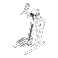
Hexagonal Hole
96
48
39
98
98
39
61
97
1
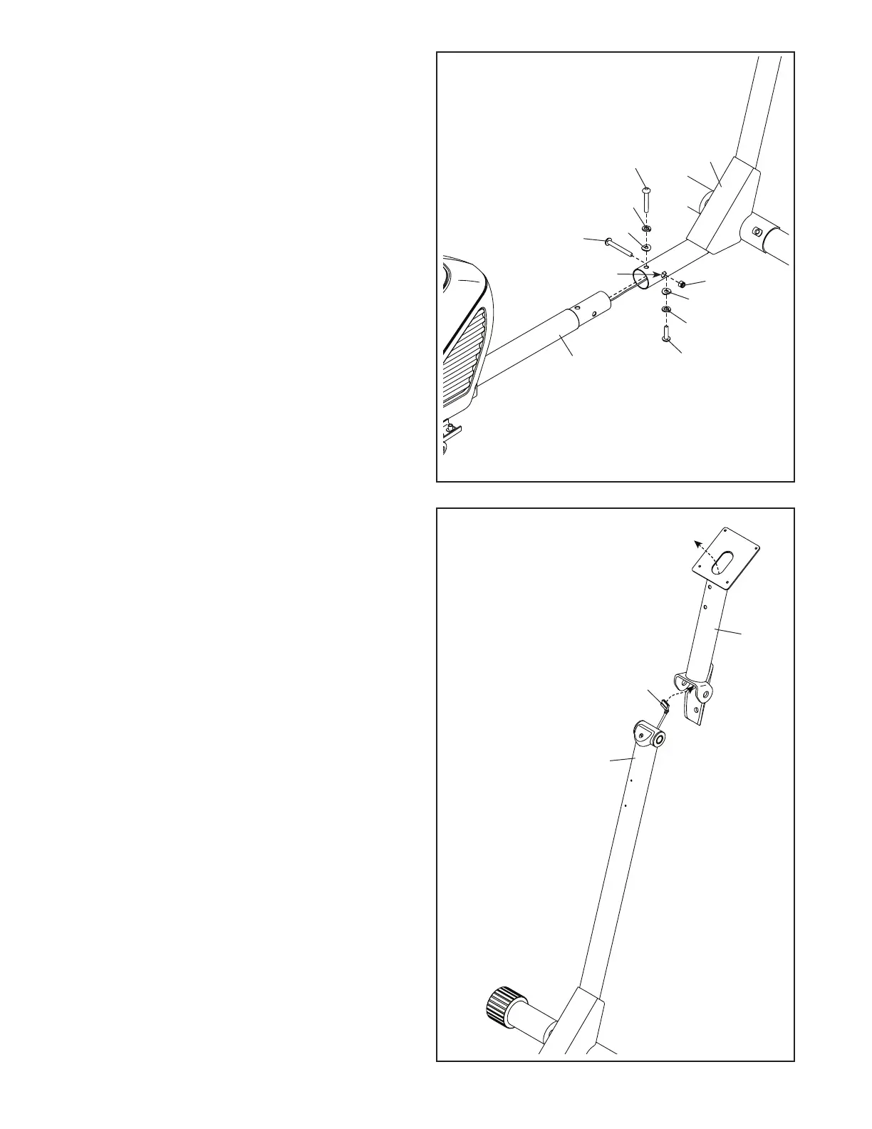
5. Tip: Avoid pinching the wires. Slide the Front
Frame (23) onto the Rear Frame (1).
Attach the Front Frame (23) with an
M10 x 25mm Screw (96), an M10 Split Washer
(98), and an M10 Curved Washer (39). Do not
tighten the Screw yet.
Next, attach the Front Frame (23) with an
M10 x 54mm Screw (97), an M10 Split Washer
(98), and an M10 Curved Washer (39). Do not
tighten the Screw yet.
Then, attach the Front Frame (23) with an
M10 x 60mm Bolt (61) and an M10 Locknut (48);
make sure that the Locknut is in the hexago-
nal hole. Do not tighten the Bolt yet.
See steps 2 and 3. Make sure that the ends of
the Rear Stabilizer (6) and the Front Stabilizer
(2) are touching the floor.
Tighten the Bolt and the Screws (61, 96, 97).
Avoid pinching
the wires
6
6. Hold the Console Post (73) near the Front Frame
(23) as shown. Insert the Upper Wire (105)
upward through the Console Post.
73
105
23