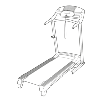
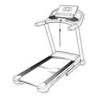
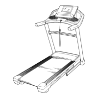
12
8
9
F
F
81
A
27
4
4
87
27
90
9
5
86
87
10
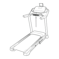
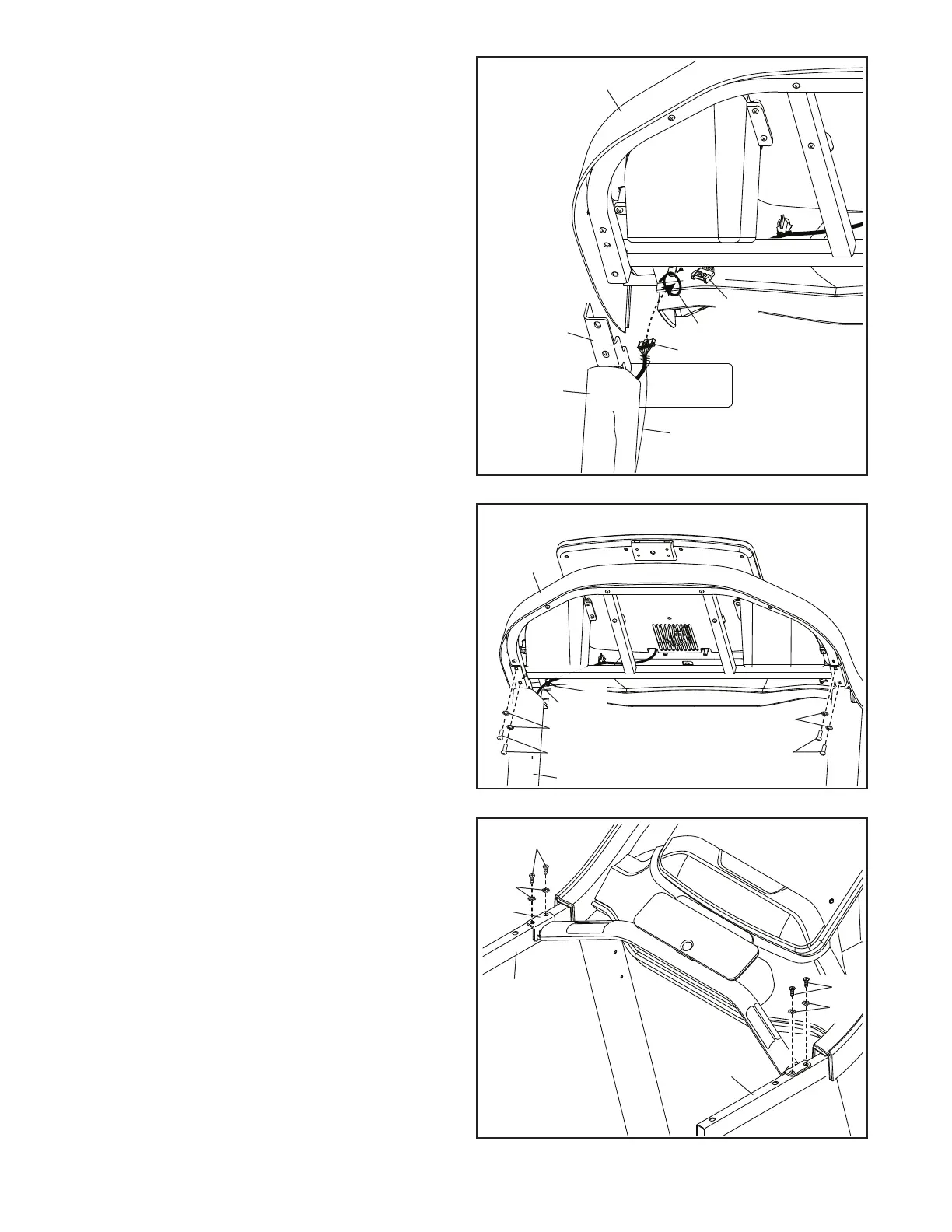
10. IMPORTANT: To avoid damaging the Pulse
Crossbar Bottom (95), do not use power
tools and do not overtighten the #10 x 3/4"
Screws (9).
Attach the Pulse Crossbar Bottom (95) to the
Handrails (86, 87) with four #10 x 3/4" Screws
(9) and four #10 Star Washers (5); start all four
Screws, and then tighten them.
95
9
5
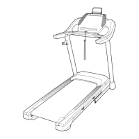
8. With the help of a second person, hold the
console assembly (F) near the Right Upright
(90).
Next, insert the Upright Wire (81) through the
indicated looped tie (G). Note: the console
assembly (F) may have two ties. If so, insert the
Upright Wire through both.
Connect the Upright Wire (81) to the wire (H)
from the console assembly (F). The connectors
should slide together easily and snap into
place. If they do not, turn one connector and try
again.
Next, set the console assembly (F) on the brack-
ets on the Right Handrail (87) and Left Handrail
(not shown); do not pinch any wires.
Then, remove any wire ties (H) from the Upright
Wire (81).
9. Attach the console assembly (F) with the four
1/4" x 1/2" Screws (4) that you removed in step
7 and four 1/4" Star Washers (27); start all four
Screws, and then tighten them.
Insert the excess Upright Wire (81) into the Right
Upright (90). Then, tighten the tie (G) around the
Upright Wire and cut off the end of the tie.
H
G
81
G
90
 Loading...