11
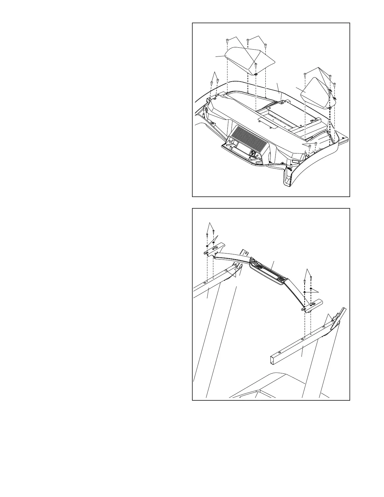
6. Set the console assembly (C) face down on
a soft surface to avoid scratching the console
assembly. Remove and save the four 1/4" x
1/2" Screws (20).
Next, identify the Left and Right Trays (104, 105).
Attach the Trays to the console assembly (C)
with eight #8 x 3/8" Screws (36); do not over-
tighten the Screws.
C
6
36
20
20
105
104
36
36
7. IMPORTANT: To avoid damaging the Crossbar
(89), do not use power tools, and do not over-
tighten the #10 x 3/4" Screws (6).
Orient the Crossbar (89) as shown. Attach the
Crossbar to the Handrails (83, 84) with four
#10 x 3/4" Screws (6) and four #10 Star Washers
(8); start all four Screws, and then tighten
them.
Then, tighten the four 5/16" x 2 1/2"
Screws (7).
89
7
8
6
7
83
8
6
84
7