V1.0 145A MULTI-PROCESS MIG-ARC-TIG WELDER 8619470
Visit www.princessauto.com for more information 13
TORCH POLARITY
Placement of the dinse connector (J) determines the torch’s polarity.
Straight Polarity or Torch Negative (-). Insert the dinse connector into the negative output
terminal (G). The torch has negative polarity in this configuration.
Reverse Polarity or Torch Positive (+). Insert the dinse connector into the positive output
terminal (I). The torch has positive polarity in this configuration.
INSTALLATION SET UP FOR ARC (STICK) WELDING
Please install the machine strictly according to the following steps.
POWER REQUIREMENTS
The power cord supplied with this welding unit is designed to handle the maximum power
required (see Specifications). Refer to the welding unit’s data plate and ensure the power
supply can meet those requirements.
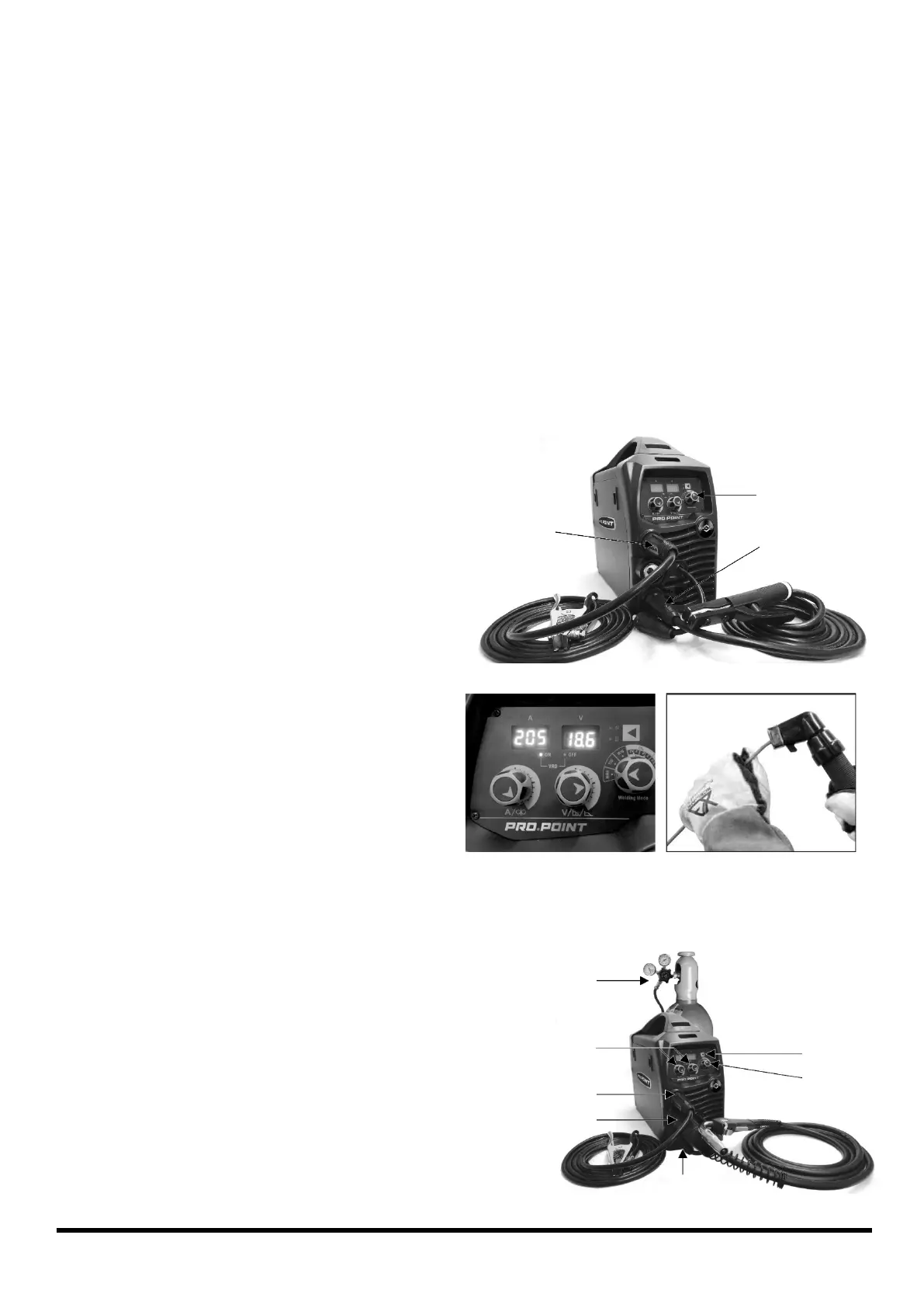
CONNECTING THE POWER LEADS
1. Connection of Output Cables - An
electrode may require either a positive or
a negative charge for optimum results.
Connect the electrode holder to the
Positive Outlet Socket (I) or Negative
Outlet Socket (G) based on the electrode
manufacturer’s information for the correct
polarity set up.
Figure 4 represents the default
configuration for ARC with the ground
lead connected to the negative lead
(Fig. 4-1) and the electrode holder
connected to the positive lead (Fig. 4-2).
The dinse connector remains unplugged.
2. Turn the power source on and select the
ARC function with the welding mode knob
(Fig. 4-3).
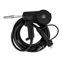
3. Set the welding current relevant to the
electrode type and size, as recommended
by the electrode manufacturer (Fig. 5)
4. Place the electrode into the electrode holder and clamp tight (Fig. 6).
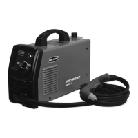
INSTALLATION & OPERATION FOR MIG WITH GAS
1. Connect the MIG Torch to the Euro connector (H)
and tighten the connector (Fig. 7-1).
2. Connect the ground lead to negative output socket
(G) (Fig. 7-2).
3. Connect the dinse connector (J) to positive outlet
socket (I) (Fig. 7-3).
4. Install the welding wire if needed (See Wire
Installation and Setup).
5. Open the valve on the gas cylinder and set the flow
to 21 CFH (Fig. 7-4).