Wiring
Reestablishing Communication
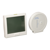
Establishing communication between master thermostat
and the base module
The thermostat and base module come factory linked out of the box.
If however, communication is lost, follow this easy- two step process to
re-establish the communication link.
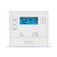
1. Press and hold the base module
button for 3 seconds. The Blue LED
will ash when ready to receive
initial signal from the thermostat.
(Base module must be powered by
24V. Blue LED will be continuously
on when 24V power is present.)
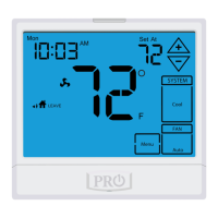
2. Hold the light key (shown here)
of the thermostat for 10 seconds,
the Blue LED on the base module
will stop ashing after
communication has been
established between base module
and the thermostat.
Step 1.
LED Relay Indicators
Blue LED
Base Module Button
Note: The blue LED on the base module
will be on when power is present. The blue
LED will ash 3 times everytime it
recieves a signal from the thermostat.
When a relay is on the corresponding LED
relay indicator will be on.
Step 2.
Light key
Note: If the base module does not
receive a signal from the thermostat for
15 minutes it will turn o all relays until
communication is reestablished. The blue
LED base module will also turn o to show
communication has been lost.
Note: If communication has been lost for
1 hour and if freeze protection is enabled,
heat and emergency heat relays will be
turned on. The heat and emergency relays
will turn on for 10 minutes every hour if
there has been a call for heat in the last 24
hours.
Important: DO NOT hold the light
button on the thermostat for more
than 10 seconds after step 2 above
has been completed. Holding the
light button down will break the
communication link and the base
module button will need to be
pressed again to reestablish
communication.
WiringWiring
Caution:
Electrical Hazard
All components of the
control system and the
thermostat installation must
conform to Class II circuits
per the NEC Code.
Warning:
Do not overtighten
terminal block screws,
as this can damage the
terminal block. A
damaged terminal block
can keep the thermostat
from tting on the
subbase correctly or
cause system operation
issues.
Installation Tip
Max Torque = 6in-lbs.
Wiring
If you are replacing a thermostat,
make note of the terminal
connections on the thermostat that
is being replaced. In some cases
the wiring connections will not be
color coded. For example, the
green wire may not be connected
to the G terminal.
Loosen the terminal block screws.
Insert wires then retighten the
terminal block screws.
Place nonammable insulation into
the wall opening to prevent drafts.
1.
2.
3.
Wiring Tips
C Terminal
The C (common wire) terminal does
not have to be connected when the
thermostat is powered by batteries.
Wire Specications
Use shielded or non-shielded 18-22
gauge thermostat wire.
Failure to disconnect the power
before beginning to install this
product can cause electrical shock
or equipment damage.
Note:
In many heat pump systems with
no emergency heat relay, a jumper
can be installed between E and
W2 to turn thermostat into a single
stage control for Emergency Heat
Operation.
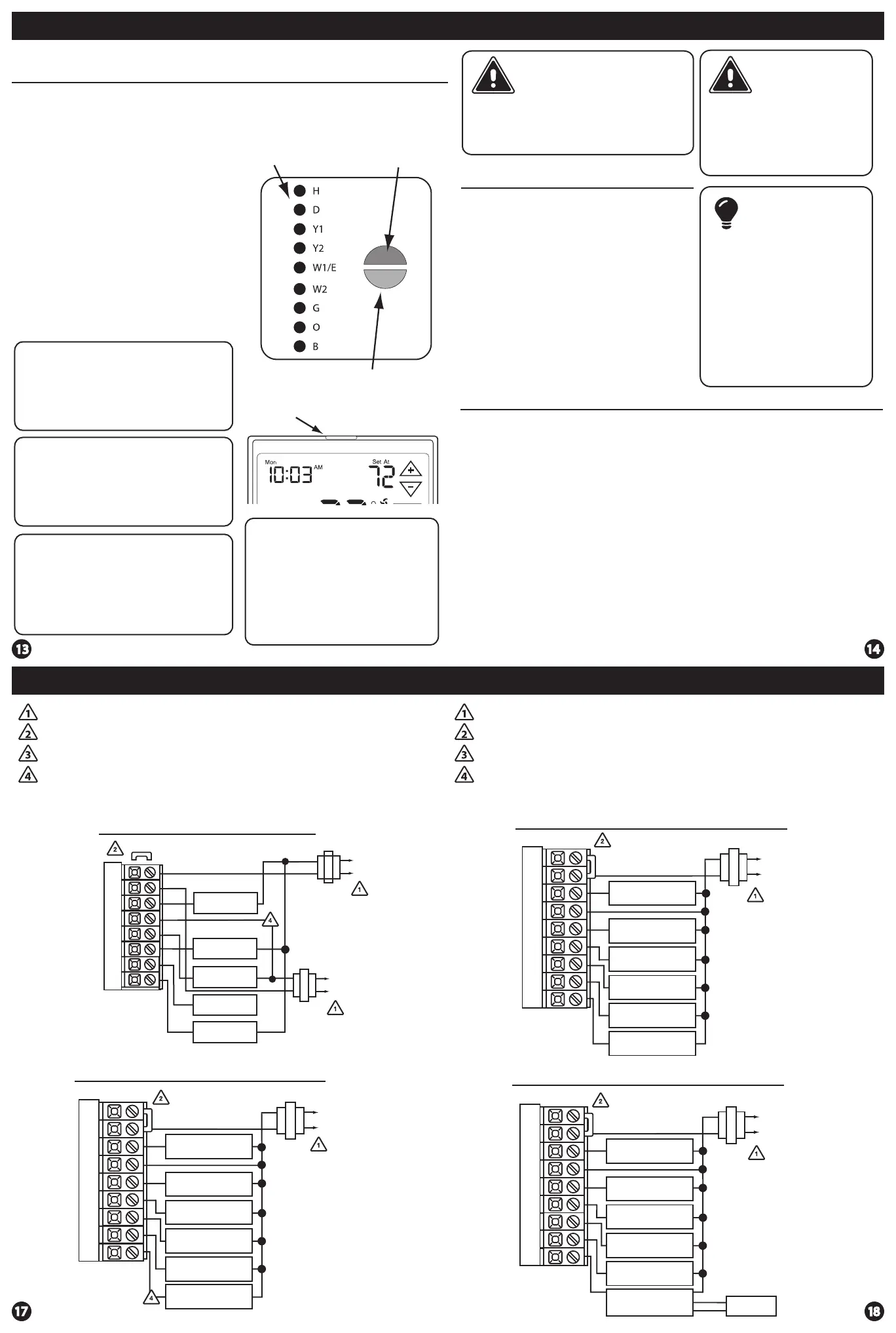
Typical 2H/2C System: 2 Transformer
REMOVE JUMPER
RC
RH
Y
C
W/E
G
W2
Y2
C
R
L2
L1(HOT)
C
R
L2
L1(HOT)
COMPRESSOR
RELAY
HEAT RELAY
FAN RELAY
HEAT RELAY 2
COMPRESSOR
RELAY 2
Power supply
Factory-installed jumper. Remove only when installing on 2-transformer systems
Use either O or B terminals for changeover valve
If DEHUM relay requires a normally-energized input, set dehumidity relay to NC in
technician setup.
Typical 2H/2C system with dehum terminal
COMPRESSOR
RELAY
FAN RELAY
HEAT RELAY 2
COMPRESSOR
RELAY 2
HEAT RELAY
DEHUM RELAY
RC
RH
Y
C
W/E
G
W2
Y2
D
C
R
L2
L1(HOT)
Power supply
Factory-installed jumper. Remove only when installing on 2-transformer systems
Use either O or B terminals for changeover valve
If DEHUM relay requires a normally-energized input, set dehumidity relay to NC in
technician setup.
RC
RH
Y
C
W/E
G
W2
Y2
H
COMPRESSOR
RELAY
FAN RELAY
HEAT RELAY 2
COMPRESSOR
RELAY 2
HEAT RELAY
HUMIDIFIER
Typical 2H/2C System with 24VAC Humidier
C
R
L2
L1(HOT)
COMPRESSOR
RELAY
FAN RELAY
HEAT RELAY 2
COMPRESSOR
RELAY 2
HEAT RELAY
24V RELAY
NORMALLY-OPEN
TERMINALS
RC
RH
Y
C
W/E
G
W2
Y2
H
DRY CONTACT
HUMIDIFIER
HUM
HUM
C
R
L2
L1(HOT)
Typical 2H/2C System with dry contact humidier
Temperature