Wiring
Wiring
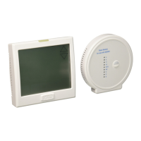
Terminal Designations on the Base Module
This thermostat is shipped from the factory to operate a conventional heating
and cooling system. This thermostat may also be congured for a heat pump
system. See the “heat pump” conguration step on page 23 of this manual to
congure the thermostat for heat pump applications.
Terminal
2 Heat 2 Cool
Conventional
System
2 Heat 2 Cool
Heat Pump
System
3 Heat 2 Cool
Heat Pump
System
RC
RH
C
B
O
G
W/E
Y
Y2
W2
Transformer power
(cooling)
Transformer power
(heating)
Transformer common
Energized in heating
Energized in cooling
Fan relay
First stage of heat
First stage of cool
Second stage of cool
Second stage of heat
Transformer power
(cooling)
Transformer power
(heating)
Transformer common
Heat pump changeover
valve energized in heating
Fan relay
First stage of
emergency heat
First stage of heat & cool
Second stage of cool
Auxiliary heat relay,
second stage of heat
Heat pump changeover
valve energized in cooling
Transformer power
(cooling)
Transformer power
(heating)
Transformer common
Heat pump changeover
valve energized in heating
Fan relay
First stage of
emergency heat
First stage of heat & cool
Second stage of cool
& second stage of heat
Auxiliary heat relay,
third stage of heat
Heat pump changeover
valve energized in cooling
Technician Setup Technician Setup
H
Humidify
D
Humidify Humidify
Dehumidify Dehumidify Dehumidify
Terminal
2 Heat 2 Cool
Conventional
System
2 Heat 2 Cool
Heat Pump
System
3 Heat 2 Cool
Heat Pump
System
If you add indoor or outdoor remote sensors to this wireless system
you must hardwire the master thermostat.
Powering the Master Thermostat
Terminal Designations on the Master Thermostat
R
24 VAC transformer power
24 VAC
transformer power
24 VAC
transformer power
C
transformer common transformer common transformer common
Typical 2H/2C System: 1 Transformer
Typical 3H/2C or 2H/1C Heat Pump System
Power supply
Factory-installed jumper. Remove only when installing on 2-transformer systems
Use either O or B terminals for changeover valve
If DEHUM relay requires a normally-energized input, set dehumidity relay to NC in
technician setup.
RC
RH
Y
C
W/E
G
W2
Y2
COMPRESSOR
RELAY
FAN RELAY
AUXILIARY
HEAT
COMPRESSOR
RELAY 2
COOL CHANGE
OVER VALVE
HEAT CHANGE
OVER VALVE
C
R
L2
L1(HOT)
RC
RH
Y
C
W/E
G
W2
Y2
COMPRESSOR
RELAY
FAN RELAY
HEAT RELAY 2
COMPRESSOR
RELAY 2
HEAT RELAY
C
R
L2
L1(HOT)
O
B
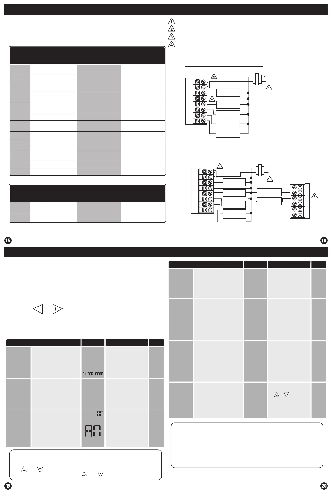
This feature allows the installer
to change the calibration of the
room temperature display. For
example, if the thermostat reads
70˚ and you would like it to read
72˚ then select +2.
OFF
This feature will ash a reminder
after the elapsed run time to
remind the user to change the
lter. A setting of “OFF” will
disable this feature.
Filter Change
Reminder
You can adjust the lter
change reminder from “OFF”
to 2000 hours of fan runtime
in 50 hour increments.
Tech Setup Steps
Room
Temperature
Calibration
0˚F
This feature allows the installer
to select the minimum run
time for the compressor. For
example, a setting of 4 will force
the compressor to run for at
least 4 minutes every time the
compressor turns on, regardless
of the room temperature.
You can set the minimum
compressor run time to “OFF”,
“3”, “4”, or “5” minutes. If 3,4
or 5 is selected, the
compressor will run for
at least the selected time
before turning o.
Minimum
Compressor
On Time
OFF
You can adjust the room
temperature display to read
up to 4˚above or below the
factory calibrated reading.
Adjustment Options Default
LCD Will Show
OFF
0
OFF
This thermostat has a technician setup menu for easy installer
conguration. To set up the thermostat for your particular application:
1. Press the MENU button.
2. Press and hold the technician setup button for 3 seconds. This 3
second delay is designed so that homeowners do not accidentally
access the installer settings.
3. Congure the installer options as desired using the table below.
Use the or keys to change settings and the next step
or previous step key to move from one step to another. Note: Only
press the DONE key when you want to exit the Technician Setup
options.
4. Press the DONE key to exit.
Keypad Lockout Note: The selected keypad lockout functionality must
be activated after exiting tech setup. If you do not perform this
procedure, all keys will function freely. To lock the keypad hold down
the and keys for 3 seconds. You will see a lock in the display. To
unlock the display hold down the and keys for 3 seconds.
CALIbRATE
The compressor short cycle delay
protects the compressor from
“short cycling”. This feature will
not allow the compressor to be
turned on for 5 minutes after it
was last turned o.
Compressor
Short Cycle
Delay
ON
Selecting “ON” will not allow
the compressor to be turned
on for 5 minutes after the
last time the compressor was
on. Select “OF” to remove
this delay.
CO
ON OF
Tech Setup Steps Adjustment Options Default
LCD Will Show
Keypad
Lockout
Keypad lockout allows you to
congure the thermostat so that
some or all of the keys don’t
function.
PA= partial keypad lockout,
which locks all the keys except
the or keys.
FU= full keypad lockout,
which locks out all the keys.
PA
See Keypad Lockout Note
PA
The swing setting often called
“cycle rate”, “dierential” or
“anticipation” is adjustable. A
smaller swing setting will cause
more frequent cycles and a larger
swing setting will cause fewer
cycles.
Cooling
Swing
The cooling swing setting
is adjustable from 0.2˚ to
2˚. For example: A swing
setting of 0.5˚ will turn the
cooling on at approximately
0.5˚ above the setpoint
and turn the cooling o at
approximately 0.5˚ below
the setpoint.
The swing setting often called
“cycle rate”, “dierential”, or
“anticipation” is adjustable. A
smaller swing setting will cause
more frequent cycles and a larger
swing setting will cause fewer
cycles.
Heating
Swing
CO
dF
0.5˚
The heating swing setting is
adjustable from 0.2˚ to 2˚.
For example: A swing setting
of 0.5˚ will turn the heating
on at approximately 0.5˚
below the setpoint and turn
the heating o at 0.5˚ above
the setpoint.
0.4˚
HE
dF
Swing Setting Tip
The second stage will turn on at 2x the swing setting. The second stage
will turn o when 1x the swing is reached. For example, if the swing
setting is .5 degrees for heating and the thermostat is set at 70˚F, the rst
stage will turn on at approximately 69.5˚F. The second stage will turn on
at 69˚F. The second stage will turn o at 69.5˚F and the rst will turn o
at 70.5˚F. If the third stage is used, it will turn on at 68.5˚F and turn o at
approximately 69˚F.
0.5
dF
0.5
EMERGENCY
HEAT
 Loading...