M-34-01-06 3/31/2016 9 DQ15D/T-DQ15D Manual
Voltage Signal Calibration
The DQ15D control measures DC voltage and
compares that measurement with a standard set
of
values in the control memory.
Les procédures de calibration nécessitent
l'enlèvement du panneau arrière du contrôle.
Ça exige aussi que le courant électrique est
allumé ce qui expose le technicien à des ten-
sions potentiellement létales. Utilisez toujours
un soin extrême et portez des gants certifiés
d'électricien quand le courrant est allumé.
Equipment Needed
Optional input boards, Item # 5447 or 5416 need-
ed.
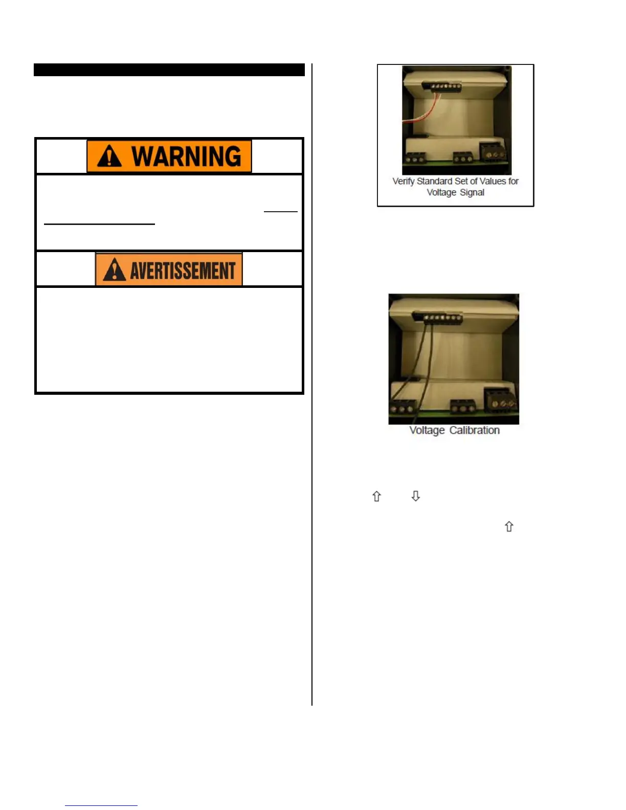
Verify Standard
Values
To restore, update or merely verify that this standard
set of values is correct, do the following:
Make sure that the DIP switch settings are OFF,
ON, OFF. See Dip Switch Settings in Configura-
tion (Setup).
The voltage signal must be connected across
terminals #1 and #2 of the Adder Board (Item #
5416 or 5447). Terminal#2 is common (negative),
and terminal #1 is the signal connection (positive).
Always observe polarity.
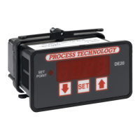
Calibration
Procedure
1 Turn OFF all power.
2 Remove rear cover.
3 Remove voltage input wiring.
4 Install a voltage calibrator or power supply to ter-
minals 1 and 2.
5 CAREFULLY restore power to the controller, en-
suring that you do not come in contact with any
exposed voltage.
6 Press and simultaneously and hold for ap-
proximately 6 seconds. The screen displays
AC.0.While the 0 is flashing, use to change this
to 22. Press SET. The control screen displays
CAL1.
7 Adjust power supply to 1.0V.
8 Press and hold SET for one second. The screen
displays Hold. Wait for display to change to CAL2.
9 Adjust calibrator to 10.0V.
10 Press and hold SET for one second. The screen
displays Hold. Wait for display to reset and display
10.0.
11 Turn OFF power to the control and remove the
calibrator. Reinstall the voltage input and the rear
cover of the control. Return the calibrated control-
ler to service
.