M-34-01-06 3/31/2016 19 DQ15D/T-DQ15D Manual
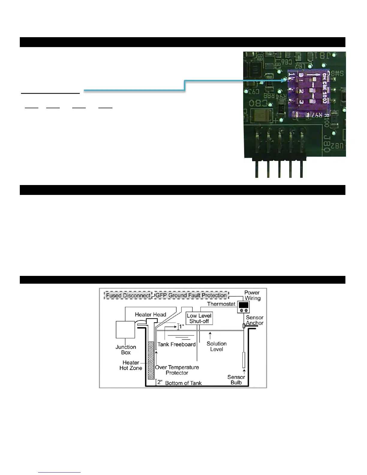
Sensor DIP Switch Settings
When using the sensor boards 5416 or 5447, an
“on-board” DIP switch must also be configured.
The DIP switch settings are as follows:
Sensor DIP Switch:
Selections
(Illustration shows
DIP switch setting for 100
ohm
RTD.)
Electrical Noise and Interference
Process Technology electronic controls are engineered, tested and manufactured to conform to Europe’s CE
levels of electrical noise and interference found in typical industrial installations. It is always possible for
electrical noise and interference to exceed the level of designed-in protection. This can happen, for example, if
arc or spot-welding equipment is close to the control or if they share a common power line. It can occur if
flame ignition systems or electrostatic precipitators are in the vicinity of the control. A more common source of
interference occurs when the control is switching inductive loads such as contactor coils, solenoids or motors.
The collapse of the magnetic field when loads such as these are switched off can create an electrical “spike”
that can cause a malfunction of the microprocessor used in the control. Even if the control doing the switching
is unaffected, a nearby control may be affected. To eliminate or minimize this problem, transient suppressors
or “snubbers” can be employed across the inductive load.
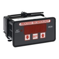
Illustration of a Typical Heater In Illustration of a Typical Heater Installation in a Process Tank
CONSULT INSTALLATION
AND
MAINTENANCE INFORMATION
FOR
SPECIFIC
INSTRUCTIONS