M-34-01-06 3/31/2016 8 DQ15D/T-DQ15D Manual
3 Wire RTD Sensor Calibration (Continued)
8 Press and simultaneously and hold for ap-
proximately 6 sec. The screen displays AC.0.
While the 0 is flashing, use to change this to 22.
Press SET. CAL1displays.
9 Press and hold SET for one sec. The screen dis-
plays Hold. Wait for the message to change to
CAL2.
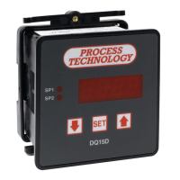
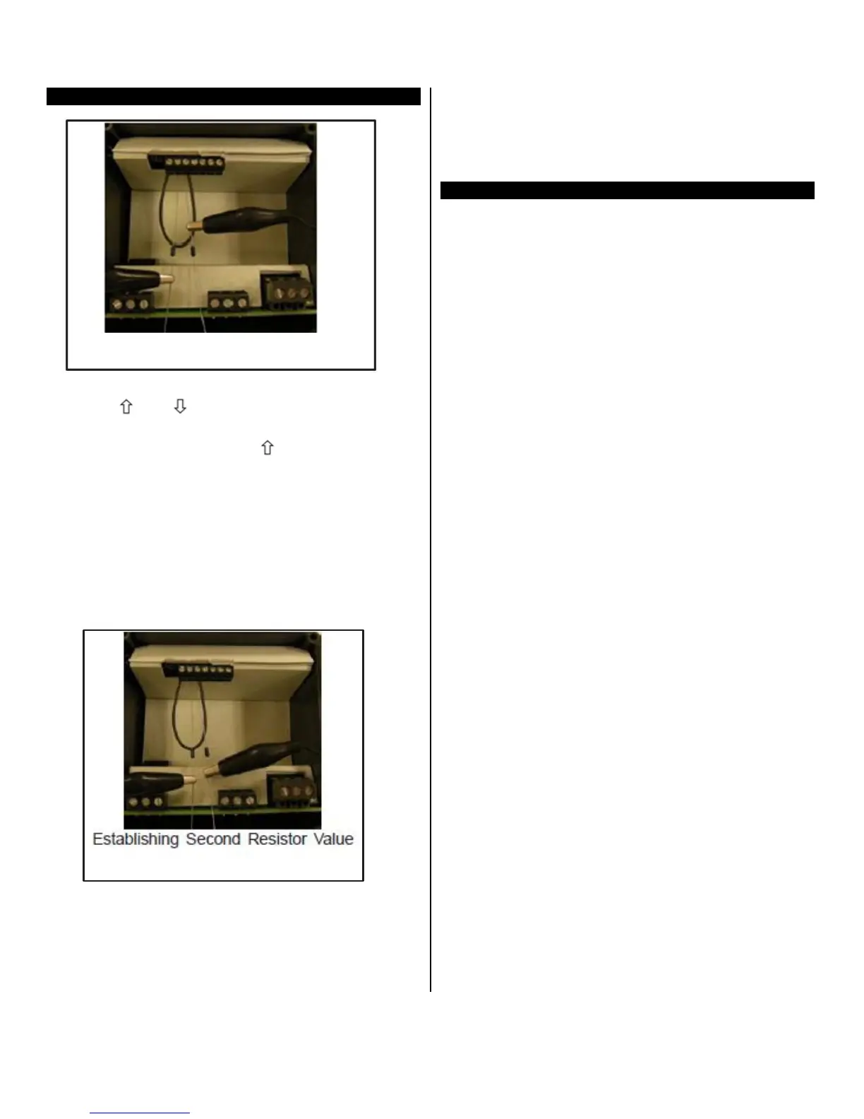
10 Proceed with CAUTION to avoid SHOCK hazard.
Remove and relocate one end of the jumper cable
to the loose end of the second precision resistor
for the second resistance value (i.e. 2000 ohms or
200 ohms), as shown.
11
12 Press and hold SET for one second. The screen
displays Hold. Wait for the display to reset. After it
resets, the approximate temperature value for the
connected precision resistors should display (i.e.
511° F or 266°C).
13 Turn OFF power to the controller and remove the
precision resistors. Retain for future use. Reinstall
the RTD sensor and rear cover of controller. Re-
turn the calibrated controller to service.
Resistance Signal Calibration
This section describes how to configure and cali-
brate DQ15D to measure pure resistance.
Equipment
needed
Refer to the calibration procedure for the 2 wire
RTD sensor for equipment needed.
Calibration
Procedure
1 From the setting configuration mode, set the U1
sensor type parameter to 12. See
Configuration
(Setup).
2 Follow the Calibration
Procedure for a 2 wire RTD
sensor. DQ15D will then measure pure resistance
from 0-1000 ohms.