M-34-01-06 3/31/2016 12 DQ15D/T-DQ15D Manual
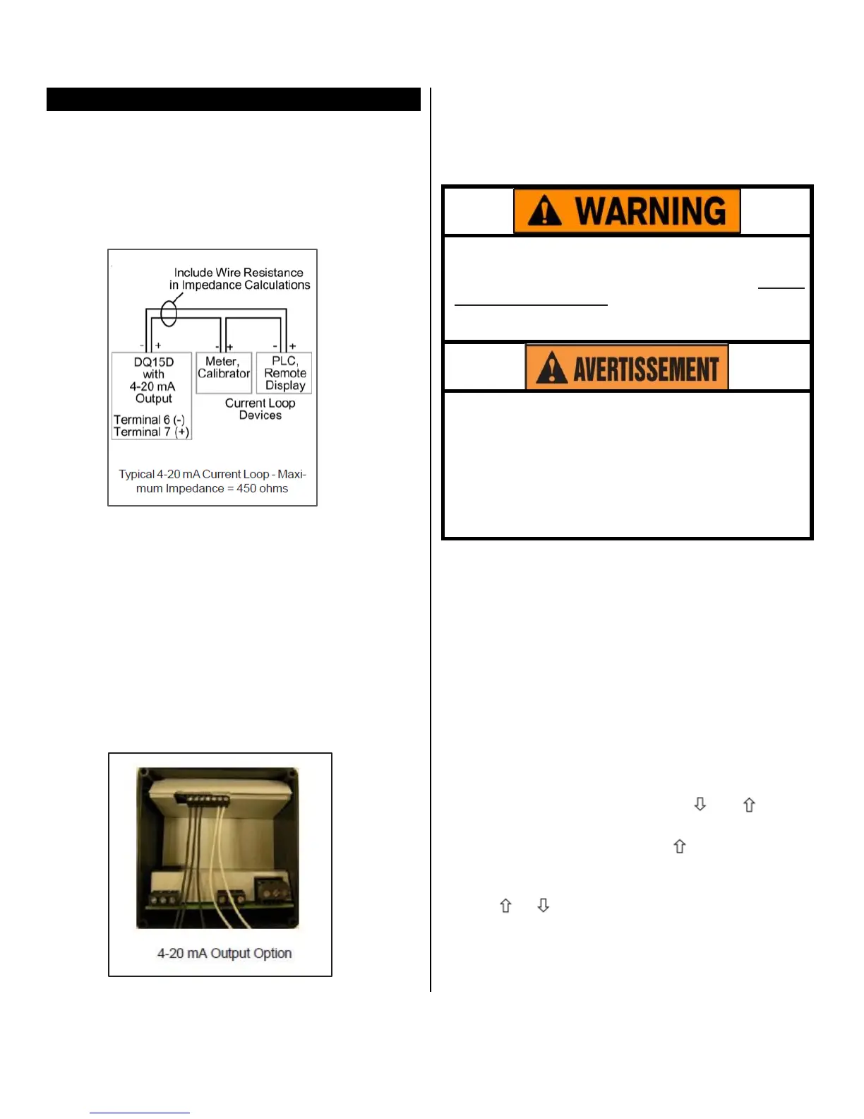
4-20 mA Output (“-M” Option)
The DQ15D is available with an optional 4-20 mA
output signal
propor
t
ional
t
o
t
he
me
a
su
r
e
d (displayed)
temperature. This option is useful for source transmit-
ting the
measured temperature to a current loop-
sensing device such as a PLC, remote intelligent dis-
play or chart recorder. Use Terminals #2 and #3 for 2
wire 1000 ohm RTD.
Factory calibration is verified using an intelligent NIST
traceable 4 digit DMM, a NIST traceable sensor cali-
brator, and an intelligent display.
The factory range setting is 0-500° F vs. 4-20 mA.
Custom ranges can be accommodated if specified at
time of order. Field calibration can use a similar ar-
rangement or a 4-20 mA calibrator for verification.
Since calibration is an involved operation, it is sug-
gested that it be performed only after determining that
the measured values differ from factory settings, or if
the output range is to be altered.
Use Terminals #2 and #3 for 2 wire
1000ohm RTD.
Equipment needed:
• Item #5416 or 5419 board.
• An NIS T traceable sensor simulator (calibrator
),
a precision
20
mA or higher calibrator/tester, or a
precision DMM for
ve
r
ificat
ion
.
Calibration procedures require the removal of
the rear cover of the
control.
It also requires that
power is ON, exposing the technician to poten-
tially lethal
voltages.
Exercise
EXTREME
CARE
and
wear tested electrician’s gloves whenever
power is on.
Les procédures de calibration nécessitent
l'enlèvement du panneau arrière du contrôle.
Ça exige aussi que le courant électrique est
allumé ce qui expose le technicien à des ten-
sions potentiellement létales. Utilisez toujours
un soin extrême et portez des gants certifiés
d'électricien quand le courrant est allumé.
Calibration Procedure:
1 Turn OFF all power.
2 Remove rear cover.
3 Remove sensor leads.
4 Install appropriate sensor calibrator, i.e. resistors
or thermocouple simulator.
5 Remove ONE lead of the 4-20 mA output wire and
install the DMM or tester in series with the external
loop and this terminal. OBSERVE POLARITY.
6 Restore power to control.
7 Verify basic instrument sensor input accuracy by
simulating various sensor inputs and observing the
display values. If out of tolerance, perform appro-
priate sensor calibration before proceeding.
8 Simultaneously press and hold and for ap-
proximately 6 sec. The screen displays AC.0.
While the 0 is flashing, use to enter 33. The
screen changes to display L followed by the cur-
rent lower process limit, i.e. 0°, -20°, 0V, etc.
9 Use or to alter the lower display value. Press
SET to store the new value. The display will then
read hexadecimal 2AAA or 4.0mA, verify that this
is the value displayed on your
4-20 mA calibra-
tor/tester or DMM.