M-34-01-06 3/31/2016 4 DQ15D/T-DQ15D Manual
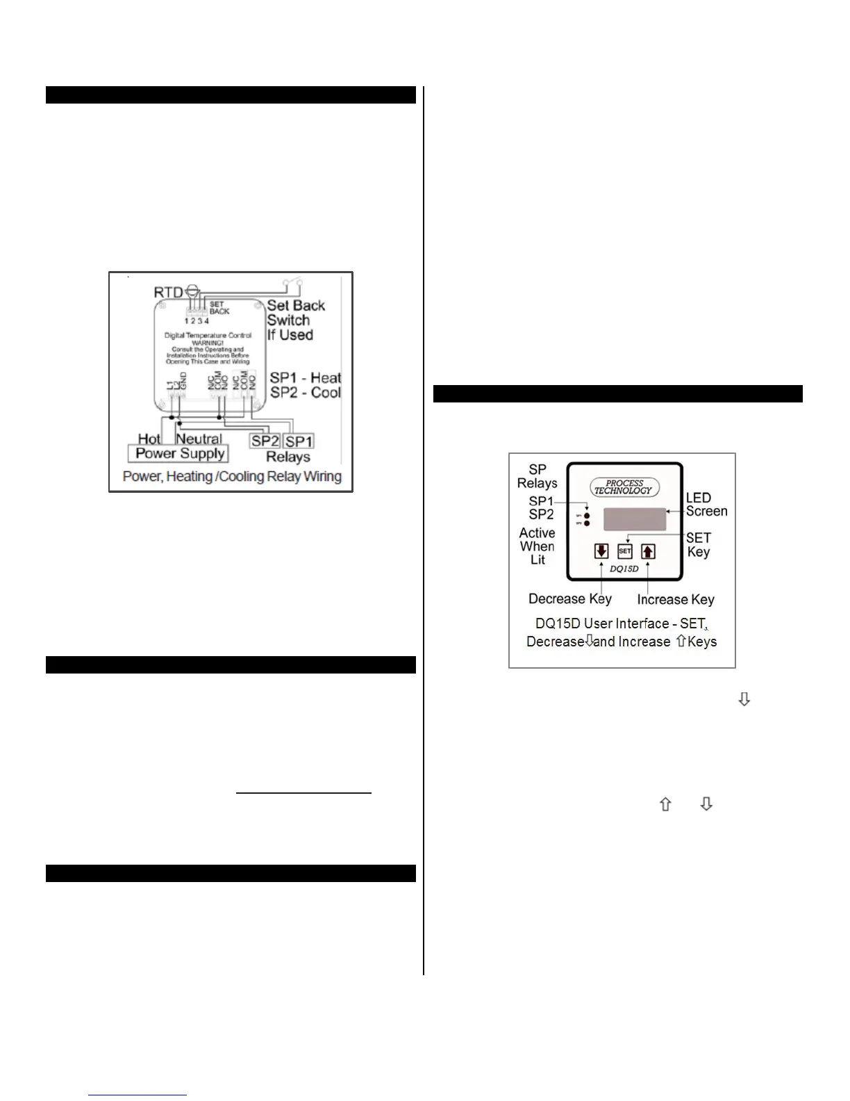
Power and Relay Wiring Procedure
Unit is intended for a single power source. To com-
plete the wiring procedure, you will need these tools
and materials:
1. #2 Phillips head screwdriver.
2. 1/8” (x-small) straight blade screwdriver.
3. Power supply wire, 18 awg minimum.
4. Relay connection wires (see state and local elec-
trical requirements for proper 65ºC wire gauge).
Referring to the “Power, Heating and Cooling Relay
Wiring (rear view of controller)” illustration above, lo-
cate and identify terminal locations for the power sup-
ply voltage, the set point relay, and the appropriate
sensor. Connect wires into their designated terminals
and tighten the retaining screw which will secure the
wire into place.
Extending Wiring
The factory supplied 1000 ohm RTD sensor can be
extended using standard electrical hookup wire (22
awg or larger). The effect of additional 22 awg sensor
wire length on control calibration is approximately 1ºF
for every 65 feet.
Note:
This does not apply
to
THERMOCOUPLES.
You
MUST use specific
thermocouple wire when
extend-
ing the sensor wire length. Use of incorrect exten-
sion wire can cause hazardous operating
conditions.
Relay Control Set Points
Before operation, you must program Set Points or tem-
perature limits.
When DQ15D reaches the Set Point it will energize one
or both relays.
SP1 Heat Set Point for normal Heating Mode opera-
tion. Controls SP1 relay.
SP2 Cool Set
Point
for normal Cooling Mode opera-
tion. Controls
SP2 relay.
P Power Save Set Point for a second heating Set
Point
lower than SP1 Heat Set Point. Optional; you
must enable Power Save
feature. Controls SP1 relay.
A Alarm Set Point to establish an Alarm Condition if
temperature reaches the
Alarm
Set Point (higher
than SP1 Set Point). The screen displays a flashing
AAA in
an Alarm Condition. Optional; you must ena-
ble Alarm feature.
Controls SP1 and SP2 relays.
Note: The units displayed, ºC, ºF, Hz, volts, mA or
ohms are established during the setup of the con-
troller.
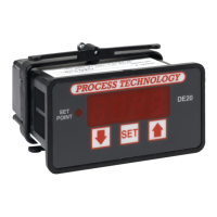
View/Change Set Points
The screen normally displays the actual process
temperature.
SP1 - Heat Set Point
1 To view the SP1 SET POINT value, press once
and release. For seven seconds, the letter H and a
decimal point followed by the numeric SP1 value
display. (After seven seconds the display returns
to normal.)
2 To alter the Set Point value, press SET while the
Set Point value displays (value will flash).
3 Once the value flashes,
use
or to change
the value.
4
Within 5
seconds
after changing the value, press
SET again to lock the new value into memory.
Note: If the “SET” key is not pressed within 5 sec-
ond
s
,
t
h
e
n
e
w
va
lu
e
will
b
e
lo
st a
nd
t
h
e set
poin
t value
will revert to its previous setting.