This document describes the ProCom Blower Accessory, Model #FIB100, an electrical component designed to enhance the operation of various fireplace models.
Function Description:
The ProCom Blower Accessory is designed to circulate warm air from a fireplace into the room, improving heating efficiency. It operates by drawing in cooler room air, passing it over the fireplace's heat exchanger, and then expelling the warmed air back into the living space. The blower can be operated in two modes: manual (MAN) for continuous operation or automatic (AUTO) where it is controlled by a temperature sensor, turning on and off based on the fireplace's heat output. This accessory is intended for use with specific ProCom fireplace models, including CRHFD28TCM-6-AU (Item # 0309527), CRHFD32RT-M-MO, FBD28, FBD32 series, PC32VFC, and PC36VFC.
Important Technical Specifications:
- Electrical Connection: The blower requires a 15 amp, 120 Volt, 60 Hz circuit with a properly grounded outlet. It is recommended that the fireplace be on a dedicated circuit to prevent tripping circuit breakers or blowing fuses due to other appliances.
- Extension Cord Usage: If an extension cord must be used, it must be UL/CSA certified, rated at 10A (1250W), 125V maximum, with 16 AWG minimum, and constructed with two current-carrying conductors with ground. A heavy-duty extension cord with the shortest possible length (not longer than 50 ft. or 15.2 m) is recommended. Coiling or covering the extension cord is prohibited.
- Grounding: The heater is designed for 120 volts. The cord has a three-prong grounding-type plug. An adapter (shown as C in Fig. 20) is available for connecting three-blade grounding-type plugs to two-slot receptacles. The green grounding lug from the adapter must be connected to a permanent ground, such as a properly grounded outlet box. The adapter should not be used if a three-slot grounded receptacle is available. Electrical outlet wiring must comply with local codes and other applicable regulations (CSA C22.1 Canadian Electrical codes or National Electric Code, ANSI/NFPA No. 70 for USA installations) to reduce the risk of fire, electrical shock, and injury.
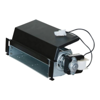
- Components: The package includes a Power Cord (A), Blower (B), Temperature Sensor (C), Connect Wire (D), and Rocker Switch (E). Hardware includes M4.2X8 Screws (AA), Cable Ties (BB), and M4.0X8 Screws (CC).
- Wiring Diagram (Simplified): The electrical wiring diagram shows connections for ~120V 60Hz input, a power cord, bushing strain relief, fan, temperature limiter, and a rocker switch with AUTO, OFF, and MAN positions. The fan is connected to the rocker switch, which in turn is connected to the power supply via a temperature limiter.
Usage Features:
- Installation: Installation involves several steps, including removing the upper firebox and heat insulation board cover, affixing the temperature sensor, inserting wires, connecting the temperature sensor with the connect wire, and then reassembling the firebox. The blower is then inserted into the bottom space of the burner pan, fixed onto brackets, and secured with screws. The blower is then mounted onto the blower access panel (for PC32VFC and PC36VFC series). The power cord is attached to the fireplace, and the grounding terminal is affixed. Finally, the male port of the blower is inserted into the corresponding female port, the port and shell board are connected with a linker into the three wires with a protecting jacket (red, yellow, and black with grounding label), and the protecting jacket is inserted into the rocker switch. The rocker switch is then pushed into the hole on the panel. The male port of the black power supply wire (P2) is inserted into the corresponding female port (P2), and the female port of the white power supply wire (P1) is inserted into the corresponding male port (P1).
- Operation Modes: The rocker switch allows selection between three modes:
- MAN (Manual): The blower remains constantly on, circulating air continuously.
- AUTO (Automatic): The blower is controlled by the temperature sensor, turning on when the fireplace reaches a certain temperature and off when it cools down.
- O (Off): The blower is turned off.
- Safety Warnings:
- Read all instructions and warnings carefully before installation and use to prevent electric shock, fire hazards, and to maintain warranty validity.
- Unplug the appliance when not in use.
- Do not operate if the cord, plug, or appliance is damaged, or if it malfunctions, has been dropped, or damaged in any manner.
- Repairs should only be carried out by a qualified service person.
- Do not modify the appliance.
- Parts removed for servicing must be replaced before operating the appliance again.
- Do not use outdoors.
- Do not locate near bathtubs or other water containers.
- Do not run cords under carpeting or cover with throw rugs. Arrange cords away from traffic areas to prevent tripping.
- To disconnect, turn controls to off and remove the plug from the outlet.
- Do not insert foreign objects into ventilation or exhaust openings.
- Do not block air intakes or exhaust.
- Use only as described in the manual to prevent fire, electric shock, or injury.
- Do not use if any part has been under water; call a qualified service technician.
Maintenance Features:
- Disconnection: Always disconnect the appliance from the main power supply and allow it to cool before any servicing operation.
- Lubrication: The motors used for the fan heater and flame blower are pre-lubricated for extended bearing life and do not require further lubrication.
- Cleaning: Periodic cleaning/vacuuming of the appliance around the air intake and exhaust, as well as the fan heater, is recommended. For heavy or continuous use, periodic cleaning should be done more frequently.
- Troubleshooting: If the heater blows alternating cold and warm air, check the fan for free movement and for debris restricting airflow. If the fan does not move freely, the unit must be turned off, and the fan replaced immediately to prevent further damage.
- Replacement Parts: Use only original replacement parts to protect warranty coverage. For parts under warranty or not under warranty, call customer service at 1-877-886-5989 (8:00 a.m. - 4:30 p.m., EST, Monday - Friday) or e-mail customerservice@usaprocom.com. When calling, have your name, address, model and serial number of the heater, how it was malfunctioning, type of gas used (Propane/LP or Natural gas/NG), purchase date, and the replacement part number ready. Defective parts may need to be returned to the factory.
The warranty requires registration within TEN (10) days of installation. Keep the serial number and a copy of the record. Always specify model and serial numbers when communicating with customer service. The warranty applies to the original owner and is not transferable.
- Limited Warranty: Pro-Com warrants this product to be free from defects in materials and components for TWO (2) years from the date of first purchase, provided the product has been properly installed, operated, and maintained in accordance with all applicable instructions.
- Responsibility of Owner: The warranty is extended only to the original retail purchaser. The warranty covers the cost of part(s) required to restore the heater to proper operating condition and an allowance for labor when provided by a Pro-Com Authorized Service Center. Warranty part(s) MUST be obtained through authorized dealers of this product and/or Pro-Com who will provide original factory replacement parts. Failure to use original factory replacement parts voids this warranty. The heater MUST be installed by a qualified installer in accordance with all local codes and instructions furnished with the unit.
- What is Not Covered: This warranty does not apply to parts that are not in original condition because of normal wear and tear or parts that fail or become damaged as a result of misuse, accidents, lack of proper maintenance or defects caused by improper installation. Travel, diagnostic cost, labor, transportation, and any and all other such costs related to repairing a defective heater will be the responsibility of the owner. THE FULL EXTENT ALLOWED BY THE LAW OF THE JURISDICTION THAT GOVERNS THE SALE OF THE PRODUCT, THIS EXPRESS WARRANTY EXCLUDES ANY AND ALL OTHER EXPRESSED WARRANTIES AND LIMITS THE DURATION OF ANY AND ALL IMPLIED WARRANTIES, INCLUDING WARRANTIES OF MERCHANTABILITY AND FITNESS FOR A PARTICULAR PURPOSE, TO TWO (2) YEARS ON ALL COMPONENTS FROM THE DATE OF FIRST PURCHASE. PRO-COM'S LIABILITY IS HEREBY LIMITED TO THE PURCHASE PRICE OF THE PRODUCT AND PRO-COM SHALL NOT BE LIABLE FOR ANY OTHER DAMAGES WHATSOEVER INCLUDING INDIRECT, INCIDENTAL OR CONSEQUENTIAL DAMAGES. Some states do not allow a limitation on how long an implied warranty lasts or an exclusion or limitation of accidental or consequential damages, so the above limitation on implied warranties, or exclusion or limitation on damages, may not apply to you. This warranty gives you specific legal right, and you may also have other rights that vary from state to state.