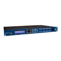
11
6. ESC button
Press this button to exit from the current menu and return to the Run time mode screen.
7. Processing menu buttons
ROUTING
Use the ROUTING button to enter the routing menu (the ROUTING button lights). In this menu you can set the signal path for each
output.
LEV - level setting
Use the LEV button to enter the levels menu (the LEV button lights). In this menu you can set the level and phase for each input and
output.
XOVER - crossover filters
Use the XOVER button to enter the crossover menu (the XOVER button lights). In this menu you can set the HP or LP filter parameters
for each output.
DELAY
Use the DELAY button to enter the delay menu (the DELAY button lights). In this menu you can set the delay time for each input and
output.
SETUP
Use the SETUP button to enter the setup menu (the SETUP button lights). In this menu you can set the various general parameters.
GEQ - graphic equalizer
Use the GEQ button to enter the graphic equalizer menu (the GEQ button lights). In this menu you can set the equalization of each input.
PEQ - parametric equalizer
Use the PEQ button to enter the parametric equalizer screen (the PEQ button lights). In this screen you can set the equalization of
each input and output.
DEQ - dynamic equalizer
Use the DEQ button to enter the dynamic equalizer screen (the DEQ button lights). In this screen you can set the dynamic equalization
of each input.
DYN - dynamic processors
Use the DYN button to enter the dynamic menu (the DYN button lights). In this menu you can set the signal dynamic processing,
compression and limiting, of each input and output.
SPLM - level manager
Use the SPLM button to enter the level manager menu (the SPLM button lights). In this menu you can set the level management for
each input and output.
RTA - real time analyzer
Use the RTA button to enter the analyzer menu (the RTA button lights). In this menu you can set the level for the RTA MIC input.
8. Input meters
The input meters monitor the input level of either analog or AES-EBU inputs, depending on the input mode set in the Setup Menu.
Optimal signal-to-noise performance is obtained when the average input level consistently lights the -12dBu (green) and intermittently
lights the -6dBu (Yellow) LED indicators. As the PC260 is a digital audio device, the digital clipping produces very unpleasant results,
so the Clip (red) LED should never light. If the PC260's input does clip, reduce the output level of the connected mixer. The -6dB PAD
button at the rear panel can be used for adjusting the input level also.
9. A - B input MUTE buttons
Each input channel has a lighted Mute button. Pressing the Mute button turns off the input of that channel. The button lights red as
an alert. Press the Mute button again to restore the output channel’s signal.
10. A - B input EDIT buttons
Use these buttons to access the editing of the input's parameter (the buttons light blue when pressed). Pressing these buttons
while in Run time mode, you enter the LEVEL menu (the LEV button also lights) where you can adjust the level of the selected input.
If a processing button, such as DELAY, GEQ, PEQ, DEQ, DYN, has been previuosly selected, pressing the edit button you choose the
channel to process.
11. Output meters
Each output channel has a four-segment VU meter. Meter withdrawal point can be pre or post mute, as set on SETUP page. The red
segment indicates that limiting is being applied to the output channel if the limiter is engaged or, if the limiter is disabled, indicates
clipping of the D/A converters, which should be avoided by adjusting the Output Level.
It is important to understand how the meters work and what they are displaying. The Output Levels are displayed as “dB to Limiter
Threshold”. In other words, the meters will display the headroom between the output level and the limiter threshold. When viewed in
conjunction with the gain reduction meters in the dynamic menu of the selected channel (use DYN button), this provides a complete
display of level and headroom before and after limiting has been engaged to allow system levels to be optimized. This also means
that the output metering will be displayed differently depending on the limiter threshold setting.
12. Output MUTE buttons
Each output channel has a lighted Mute button. Pressing the Mute button turns off the output of that channel. The button lights red
as an alert. Press the Mute button again to restore the output channel’s signal.
13. Output EDIT buttons
Use these buttons to access the editing of the output's parameter (the buttons light blue when pressed). Pressing these buttons while
in Run time mode, you enter the LEVEL menu (the LEV button also lights) where you can adjust the level of the selected channel. If a
processing button, such as XOVER, DELAY, PEQ, DYN, has been previuosly selected, pressing the edit button you choose the channel
to process.