12
14. RTA MIC input
This balanced XLR input is fitted a phantom power to supply and it can be used for connecting a condenser microphone for acoustic
measurements. This allows the PC260 to measure and display in real time the signal reproduced through the speakers system in the
acoustic environment.
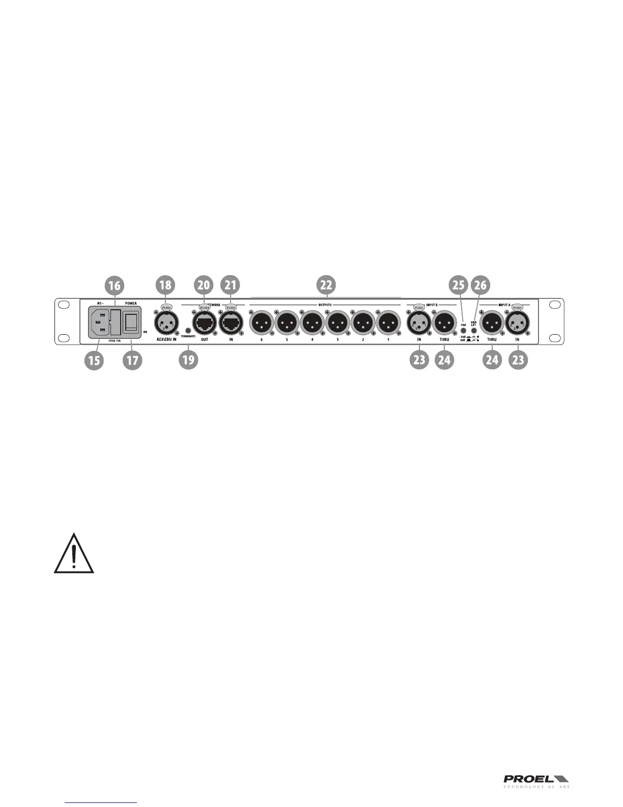
REAR PANEL
15. AC ~
The PC260 features a standard IEC A.C. inlet that will accept universal power cords. The PC260 power supply is auto-ranging and can
accept voltages from 100 - 240 V AC, 50 – 60 Hz. Only A.C. cords approved for use in your country should be connected to the PC260.
16. FUSE holder
The A.C. inlet includes a fuse holder that contains the mains fuse as well as a spare fuse. If necessary, replace the fuse only with a
specified 5x20mm, T 1 A 250 V replacement. Disconnect A.C. power before replacing a fuse. Before turning the unit back on, assess
the condition of the A.C. receptacle powering the unit. If the fuse continues to blow, refer to PROEL qualified service personnel.
17. POWER switch
The A.C. power switch turns power to the PC260 On and Off.
18. AES/EBU Digital Input
In addition to the analog audio inputs, an AES/EBU digital stereo input is provided and selectable in the SETUP menu. The input
conforms to IEC standard 60958 Type I. Connections must be made with three-conductor, 110-Ohm, twisted pair cabling and an XLR
connector. It allows to use all sampling frequencies in the range of 32-96 kHz.
19. TERMINATE switch
In a PRONET network the last connected device must be terminated (with an inner load resistance) especially in a long run cabling:
press this switch if you want to terminate the unit.
20. PRONET Network OUT connector
This is a standard RJ45 CAT5 connector (with optional NEUTRIK NE8MC RJ45 cable connector carrier), used for transmission of remote
control data over long distance or multiple unit applications. See PRONET section further in this manual.
21. PRONET Network IN connector
This is a standard RJ45 CAT5 connector (with optional NEUTRIK NE8MC RJ45 cable connector carrier), used for transmission of remote
control data over long distance or multiple unit applications. See PRONET section further in this manual.
22. Balanced XLR Output connectors
Each output channel has an electronically balanced XLR connector for the connection to the system's amplifiers.
IMPORTANT: Care must be taken to assure that each output is connected to an appropriate amplifier and loudspeaker to
avoid damage or unexpected results. Note that a new preset may change the assignment of channel and its frequency
range. For instance an output assigned to Hi frequency speakers in one preset, may be assigned as a sub output in another.
See Configurations section further on this manual.
23. Balanced XLR Input connectors
Each input has an electronically balanced, locking XLR connector. In stereo or dual modes, connections to both inputs must be made.
In mono modes, only one connection is needed, typically to Input A.
24. Balanced XLR Thru connectors
Each analog audio input is linked directly to an XLR male connector. The signal does not undergo any digital conversion or processing.
These connectors are used to pass input audio to a second PC260 used as a slave or to other audio inputs in the system.
25. – 6dB PAD switch
Input levels to the PC260 can be reduced by 6dB prior to the A/D converter to compensate for higher-level output from mixers and
other audio devices. The PC260‘s Input level Meters (8) will indicate incoming signal level and whether attenuation is required.
26. GND LIFT switch
This switch lift the ground of the balanced audio inputs from the earth-ground of the PC260. If you have HUM noise problem on the
whole loudspeaker system attached to your PC260 try to change the position of this switch. Please note that to have an effect all
cables must be balanced.