8
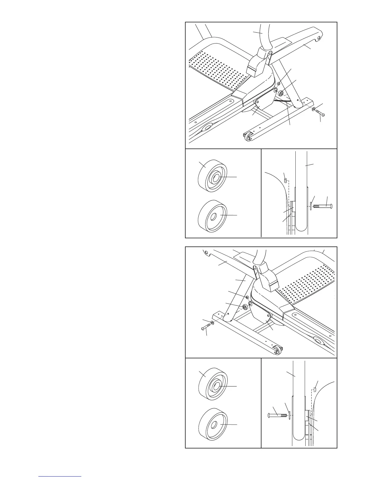
5. See the left inset drawing. Identify the two
Frame Spacers (34). Open the included packet
o
f grease, and apply grease to both sides of
both Frame Spacers. Then, identify the outer
s
ide of each Frame Spacer.
Next, hold a Frame Spacer (34) between the
Right Upright (36) and the Lift Frame (59), with
the outer side of the Frame Spacer facing the
Right Upright. Attach the Right Upright to the
Lift Frame with a 3/8" x 3 1/2" Bolt (32), a 3/8"
Washer (33), and a 3/8" Locknut (47);
do not
tighten the Bolt yet.
Then, identify the Right Base Cover (91). Slide
the Right Base Cover onto the Right Upright
(36) and turn it to the position shown.
Pull gently on the upper end of the Upright Wire
(28) to remove any slack.
5
36
91
32
32
34
34
33
47
47
59
33
59
Outer
Side
Inner
Side
34
36
6. See the left inset drawing. Identify the outer
side of the remaining Frame Spacer (34).
Hold the Frame Spacer (34) between the Left
Upright (31) and the Lift Frame (59), with the
outer side of the Frame Spacer facing the
Left Upright. Attach the Left Upright to the Lift
Frame with a 3/8" x 3 1/2" Bolt (32), a 3/8"
Washer (33), and a 3/8" Locknut (47); do not
tighten the Bolt yet.
Identify the Left Base Cover (90). Slide the Left
Base Cover onto the Left Upright (31) and turn it
to the position shown.
6
31
90
32
32
34
34
33
47
47
59
33
59
Outer
Side
Inner
Side
34
31
28