10
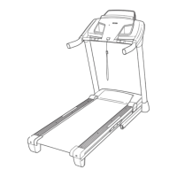
9. Slide the Right Upright Cover (86) onto the
Right Upright (85). Remove the tie from the
5/16" Cage Nut (38). If necessary, press the
Cage Nut back into place.
Hold the Right Handrail (83) near the Right
Upright (85). Insert the Upright Wire (87)
through the bracket on the bottom of the Right
Handrail. Pull the Upright Wire out of the end of
the Right Handrail.
Attach the Right Handrail (83) to the Right
Upright (85) with two 5/16" x 1" Flat Head
Screws (14), a 5/16" x 1" Bolt (4), and a 5/16"
Star Washer (13) as shown. Do not tighten the
Screws and Bolt yet.
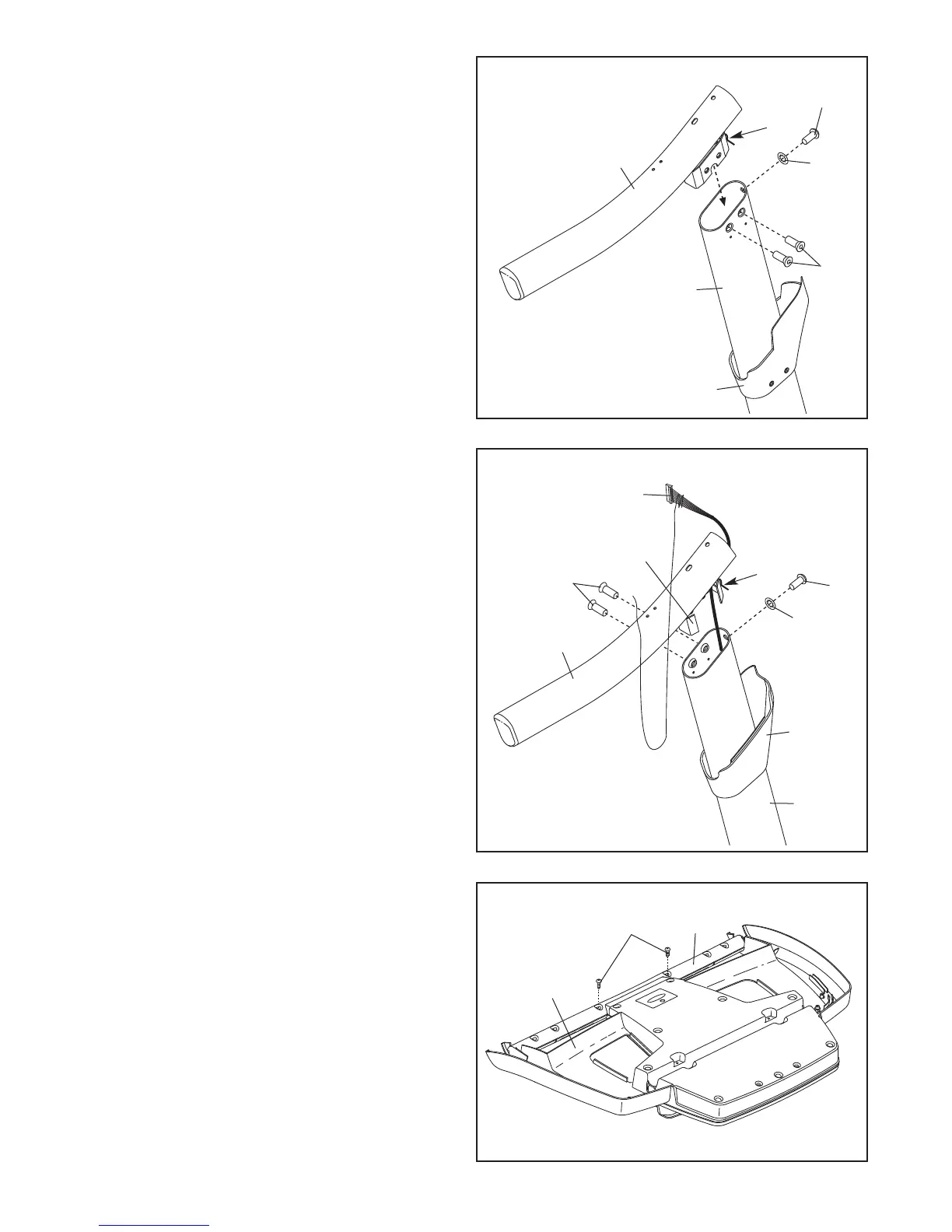
10. Set the console assembly face down on a soft
surface to avoid scratching the console assem-
bly. Remove the two #8 x 3/4" Screws (1). Lift
off the Crossbar (107). Discard the Screws.
10
107
Console
Assembly
1
38
83
Bracket
14
4
13
86
85
87
9
8. Identify the Left Upright Cover (80). Slide the
Left Upright Cover onto the Left Upright (84).
I
dentify the Left Handrail (82). Remove the tie
from the 5/16" Cage Nut (38). If necessary,
p
ress the Cage Nut back into place.
Attach the Left Handrail (82) to the Left Upright
(84) with two 5/16" x 1" Flat Head Screws (14),
a 5/16" x 1" Bolt (4), and a 5/16" Star Washer
(13) as shown. Do not tighten the Screws and
Bolt yet.
8
2
4
14
13
84
80
8
38