8
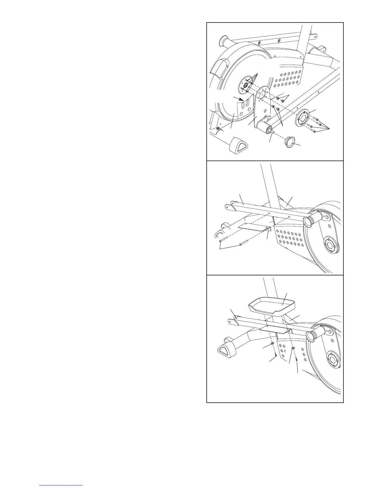
9. Identify the Left Pedal (12), which is marked with an
“L.” Attach the Left Pedal to the Left Pedal Arm (14)
with two M8 x 16mm Button Screws (91) and two M8
Split Washers (83).
Attach the Right Pedal (not shown) to the Right Pedal
Arm (75) in the same way.
14
12
91
91
83
75
83
9
8. Attach a Pedal Bracket (16) to the Left Pedal Arm (14)
with two M8 x 53mm Button Screws (84).
Attach the other Pedal Bracket (not shown) to the Right
Pedal Arm (75) in the same way.
8
84
14
75
16
7. Slide the Right Crank Arm (38) onto the four indicated
welded bolts; make sure that the Right Crank Arm is
i
n the indicated cutout in the Pedal Disk (8). N
ext,
finger tighten four M8 Jamnuts (104) onto the welded
b
olts. Then, fully tighten one of the Jamnuts, and then
tighten the Jamnut farthest from the first Jamnut. Then,
tighten the remaining two Jamnuts.
Attach a Hub Cover (48) to the Right Crank Arm (38)
with four Cover Screws (82). Then, tighten an
Adjustment Knob (45) onto the right Adjustment Pin (17).
7
38
Cutout
82
48
104
45
17
Welded
Bolts
8
104