6
5
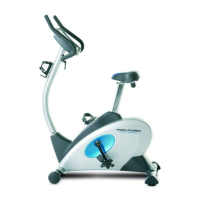
5. Make sure that there are Round Endcaps (15) on
the ends of the Rear Stabiliser (16).
Hold the Rear Stabiliser (16) against the saddle on
the rear of the Frame (13), with the square holes
facing away from the saddle. Attach the Rear
Stabiliser with two M10 x 75mm Carriage Bolts (54)
and two M10 Nylon Locknuts (44).
4
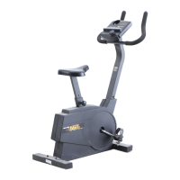
4. Make sure that there are Adjustable Endcaps (25)
on the ends of the Front Stabiliser (27).
Hold the Front Stabiliser (27) against the saddle on
the front of the Frame (13). Make sure that the
Front Stabiliser is turned so the Wheels (26) are
not touching the floor. The Wheels should touch
the floor only when the exercise bike is tipped for
moving. Attach the Front Stabiliser with two M10 x
75mm Carriage Bolts (54) and two M10 Nylon
Locknuts (44).
27
25
26
26
25
44
13
54
13
54
44
15
16
Square
Holes
15
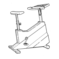
3. Attach the Handlebar (18) to the Handlebar Post
(19) with two M10 x 22mm Button Screws (55) and
two M10 Lock Washers (61).
3
19
61
55
18
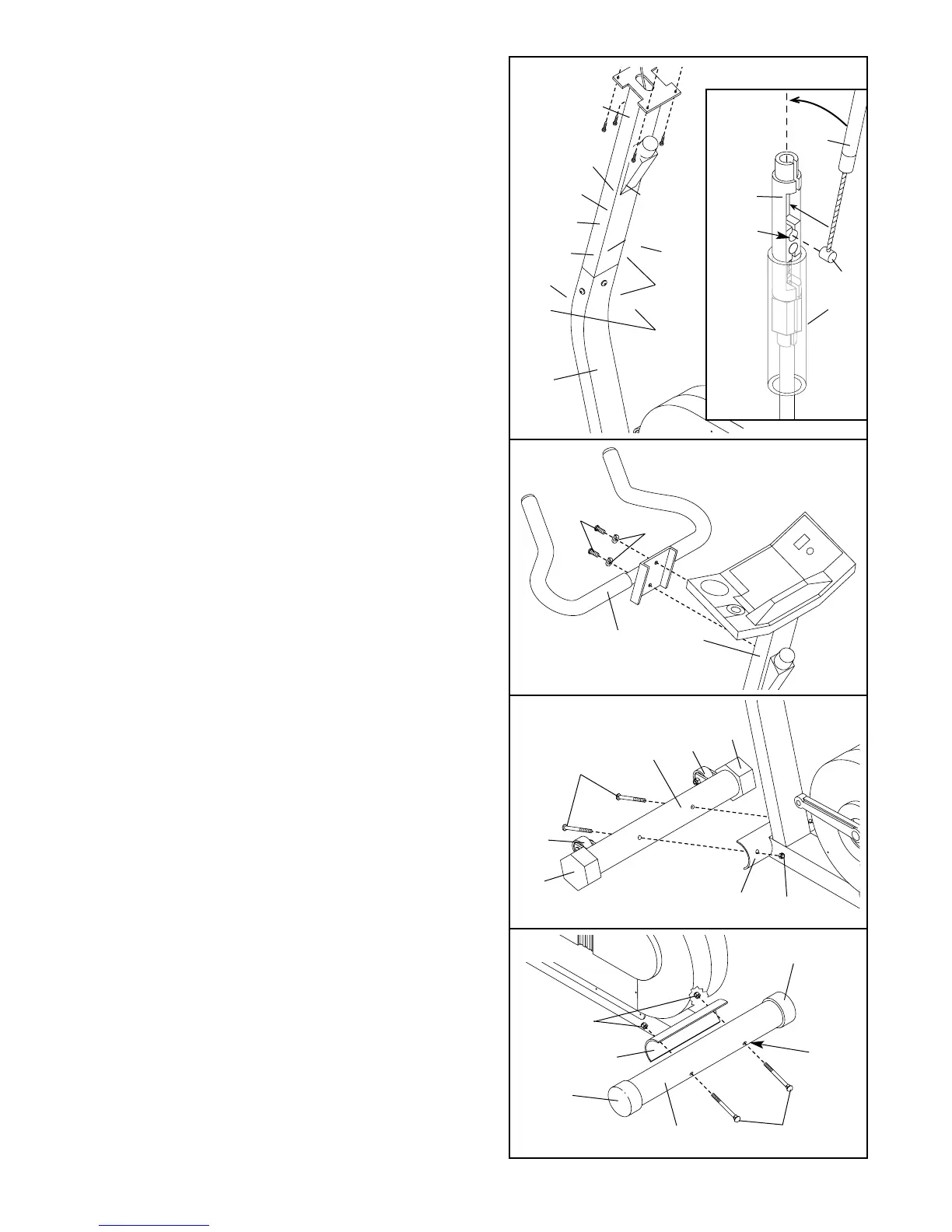
2. Refer to drawing 2a. Locate the sheath and make
sure that it remains on the Cable Connector (43).
Insert the tip of the Upper Resistance Cable (6) into
the opening in the Cable Connector as shown in the
inset drawing. Pull up on the Upper Resistance Cable
and insert it into the top of the Cable Connector.
Center the sheath on the Cable Connector.
Connect the console wire to the Reed Switch Wire
(4). Slide the Handlebar Post (19) into the Frame
(13), making sure not to pinch any of the wires
or cables. Attach the Handlebar Post with three
M10 x 22mm Button Screws (55) and three M10
Lock Washers (61).
61
61
55
55
13
4
19
43
74
6
Console
Wire
6
43
Tip
2a
Insert
Here
Sheath
Sheath
2