ASSEMBLY
Assemblyrequires Iwo persons.To'assembleth_CRO_ TRAINERe, us":.1_ ind.ud_ vid.ea_:assetteor foflow the _-_
instrucffons befow. Due 1otheweTght'oFthe GROSS TRAINERe, it shouldbe assembledin the'location whof'e it will be"
used.Pta_e'attPor_inactea,_o_;_ed,'_* _ mot_a!s.Do_otd_s_seo_thePo_,_,_te_ol_unto
assembly is co_'npleted.Make'sure to lower the'r_islance cylindersand pedals before beginning assembly; if the ,._
reslstahce cyllnders foil, Ihey may damage _theslde._ielcls. Read ea.chassemblystepand examineeach drawing .-.
care[ully. Refer tothe Part IdentificationChart a_componylngthis owner's manual, to help identi_,the h_ardware used
in assembly. Make sure that all parts a'reoriented as shown in Ihe dr_s.
The follow_ngtools "(notindude_ 9m .requ|mdfor assembly:.Iwo 8" Adjustable Wrenches _ and a
Rubber'Mailet .A smallanent oFsoapy_vateris alsoreclulred._
-3.
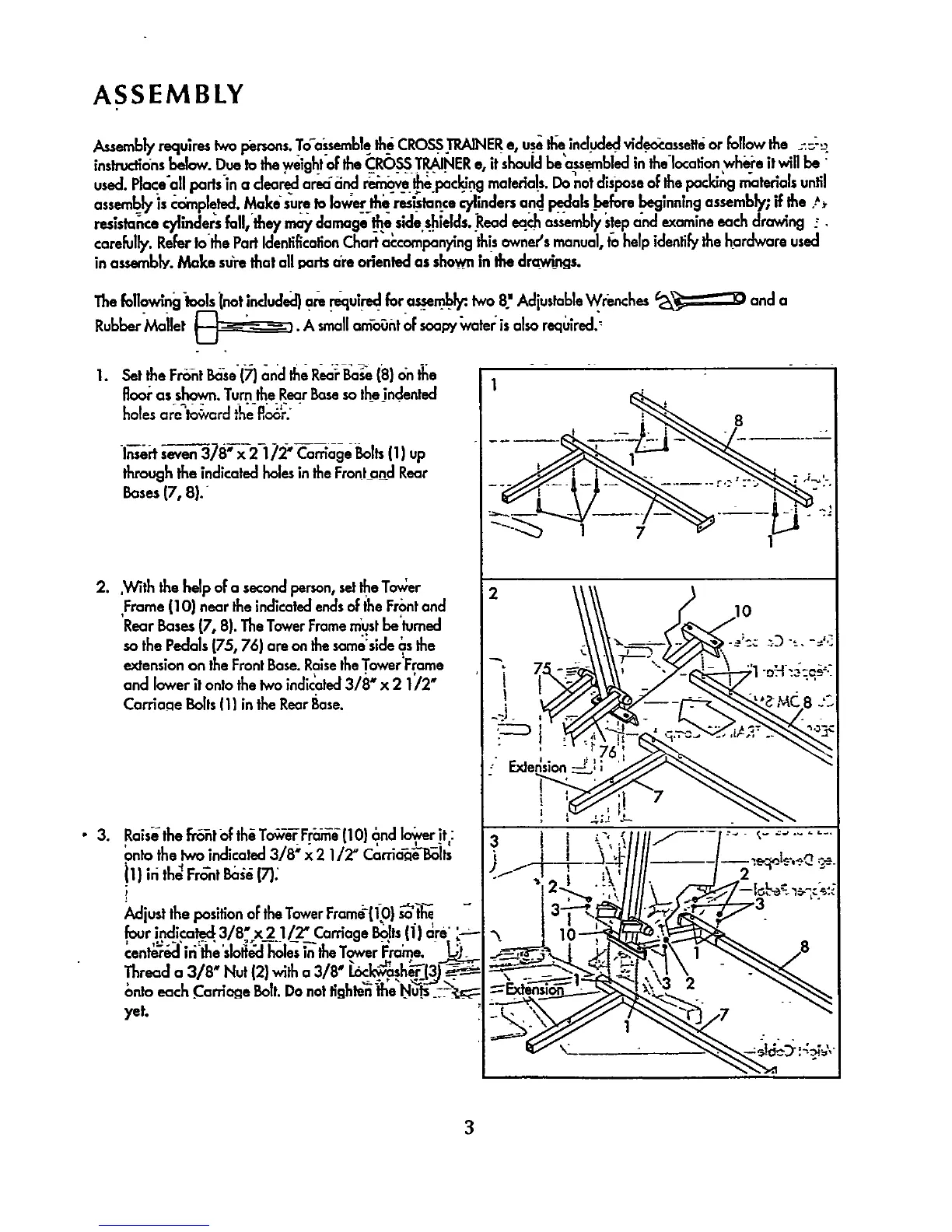
L s_ttheF_t _se(;;)_ndth,iR_ _ (8)on_e
fioor as shown.Turn the RearBaseso theindented
holesore toward the floor.
l_e_ s-_3_ 378_x-2-1 _2"Caarr[age Bolts(1) up
through the indicated holesin the Frontand Rear
Bases (7, 8}."
2..With the help of o secondperson,setIhe To_er
Frame (10) near the indicated endsof the Frontand
'Rear Bases(7, 8). TheTower Framemustbe'turned
so the Pedals (75, 76) are on thesame:side_.sthe
extension on the FrontBase. Raisethe Tower'Frame
and lower it onto the two indicated3/8" x 2 1/2"
Corriaae Bolts(1) in the Rear Base.
Rai.,,ethefr_t oFth_To,_v-e¥Fr;_ (1O}_ndI"o_verit:
ontothetwo indicated 3/8 '_x 2 1/2' Carria_"l_its
_1) iri the_FrOnt Ba_a(7).
J_djust the positionof theTowerFrame11_O}_'t_e -
four indite .h.._..3/8" x_2._I/__ Carriage Bolts(1) are'
cent_r&l'ffithe'slol_J holes_the Tower i_ra_e. _)_
Thread a 3/8" Nut {2} with a 3/8" 1.6c_h__(3)_
onto each .Carnage Bolt.Do not I_ghten_neNu'_-_:.-'_:_
yet.
1
|
1
_12"__ "'_ III1\ .,-'q_--_/--l_:_:.
"_,. _ 10 _,-_-_._ 8
! -_ _ _. "-"
3