EasyManuals Logo

ProForm PRO 2000 User Manual

ProForm PRO 2000
44 pages
To Next Page IconTo Next Page
To Previous Page IconTo Previous Page
Page #13 background imageLoading...
Page #13 background image
13
12
75
24
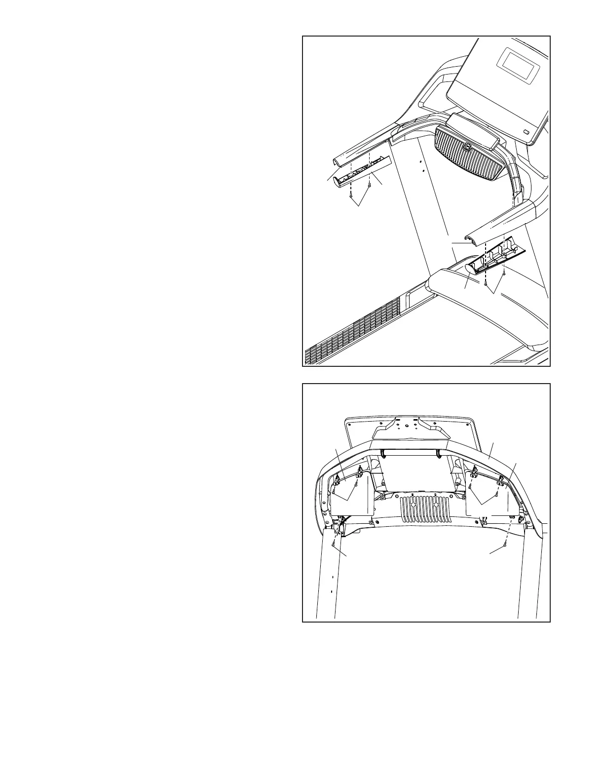
12. Attach the Left Handrail Bottom Cover (75) to the
left Handrail (74) with two #8 x 3/4" Truss Head
Screws (24); start both Truss Head Screws,
and then tighten them. Be careful not to over-
tighten the Truss Head Screws.
Attach the Right Handrail Bottom Cover (82)
to the right Handrail (74) as described above.
13
24
24
94
13. Identify the Left and Right Trays (94, 32). Attach
the Trays to the console assembly (G) with six
#8 x 3/4" Truss Head Screws (24); start all six
Truss Head Screws, and then tighten them.
Do not overtighten the Truss Head Screws.
74
74
24
82
24
24
32
G

Questions and Answers:

Question and Answer IconNeed help?

Do you have a question about the ProForm PRO 2000 and is the answer not in the manual?

ProForm PRO 2000 Specifications

General IconGeneral
Speed Range0-12 MPH
Running Surface20" x 60"
Weight Capacity300 lbs
Display7" Backlit LCD
FoldingYes
Heart Rate MonitoringEKG Grip Pulse
BluetoothYes
Cooling FanCoolAire Fan
AudioDual 2" Speakers
Incline Range-3% Decline to 12% Incline Digital Control

Related product manuals