Key No. Qty. Description Key No. Qty. Description
101 1 Console Base 117 1 Left Top Handgdp
102 1 Optic Disk 118 1 Photo Switch Nut
103 8 Ground Screw/Choke Screw 119 1 Left Bottom Handgdp
104 1 Key Clip # 1 1O" Blue Wire, 2F
105 2 Fan Screw # 1 10" Blue Wire, M/F
106 1 Fan # 1 4" Blue Wire, M/F
107 1 Console # 1 8" Green Wire, 2 Ring
108 44 Screw # 1 4" Green Wire, M/Ring
109 1 Left Tray # 1 14" Red Wire, M/F
110 1 Console Support # 1 12" Black Wire, M/F
111 1 Right Tray # 1 User's Manual
112 1 iFIT.com Wire
113 1 Hood *Includes all parts shown in the box
114 2 Motor Bracket Bolt #These parts are not illustrated
115 1 Photo Switch Screw
116 1 Left Handrail If a part is missing, call toll-free 1-888-533-1333.
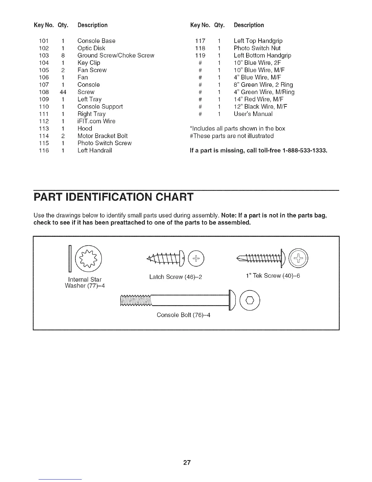
PART IDENTIFICATION CHART
Use the drawings below to identify small parts used during assembly. Note: If a part is not in the parts bag,
check to see if it has been preattached to one of the parts to be assembled.
Internal Star
Washer (77)-4
Latch Screw (46)-2
1" Tek Screw (40)-6
Console Bolt (76)-4
27