16
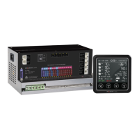
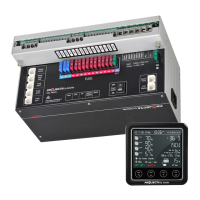
5.2 Monitor PMLCD-BT
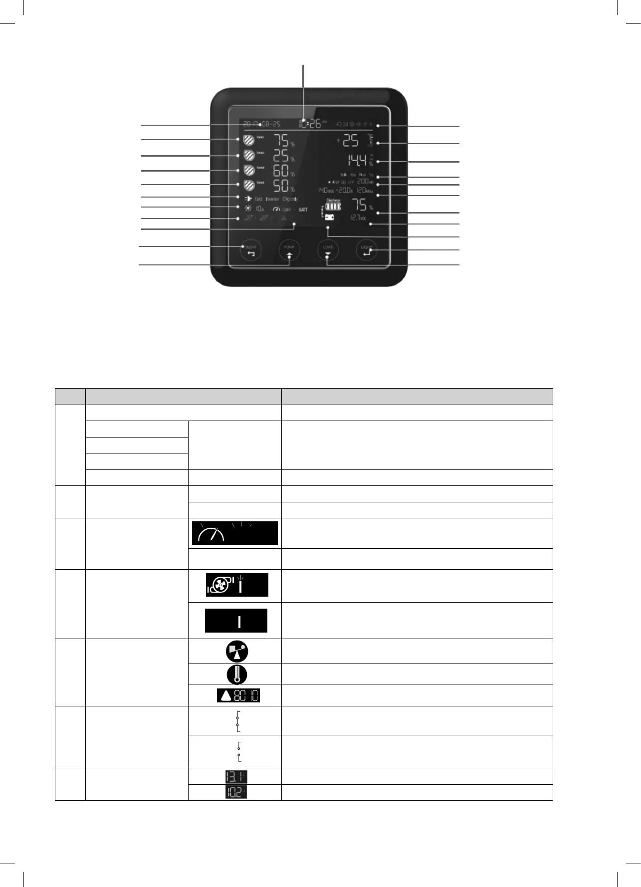
5.2.1 Monitor Symbol Explanation
No. DESCRIPTION COMMENTS
1 Water level 0%-25%-50%-75%-100%
Water Tank 1 EMPTY Flashing, the water is less than the recommended level
Water Tank 2
Water Tank 3
Water Tank 4 FULL Flashing, the gray water or waste water is more than the alarm level
2 Working Mode GRID AC grid status
CHARGE ONLY Battery charger only
3 Load Status of DC-Load switch in system: on / off
BATTERY DC loads are powered by battery
4 Water Pump Pump 1 is ON
Pump 1 is OFF
5 Alarm Error Code Overload alarm
Over temperature alarm
System error code. Refer to the error codes on page 20
6 VCR connection Voltage charging relay (VCR) is connected
Voltage charging relay (VCR) is disconnected
7 Output power Voltage of system output
Current of system output
Table 8 Symbol Explanation
Charging state
Pump/Up switch
Silent/Esc switch
Alarm error code
Water pump
Solar charge
Power Source
Water tank 4
Water tank 3
Water tank 2
Water tank 1
Date
Service battery:Type/Capacity
Service battery: Voltage/Current/Time to go
Service battery SOC (State of Charge)
Voltage of vehicle battery
VCR connection
Light/Enter/Setting switch
Time
Load /Down Switch
Setting/Volume/Bluetooth
Temperature
Output power
Load
ON
!
Figure 22 An overview of monitor
The PMLCD-BT monitor can be paired to a smart phone via the BWI-PM300 App. This App will display the battery parameters, water tank
levels, allow pump control and load isolation. Refer to the PM300-BT App Operation Manual for Bluetooth pairing procedure.
 Loading...