5
Failure indicator
Failure indicator flashes in case of failure of the connection devices.
For failure information please check the Controller Manual.
Alarm
Fault audible alarm, could be activated or deactivated.
Communication indicator
Indicate communication status when MT50 is connected with the controller.
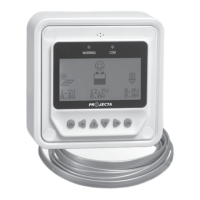
Display screen
Man-machine interaction operation interface.
Buttons
The Meter buttons includes four navigation buttons and two operational buttons.
See the specific directions in the Operation section of this manual.
RJ45 communication and power interfaces
Communication and power supply cable interfaces, used for communication connection
with controllers.
Note: Please use the communication plug which is marked with “MT” to connect MT50
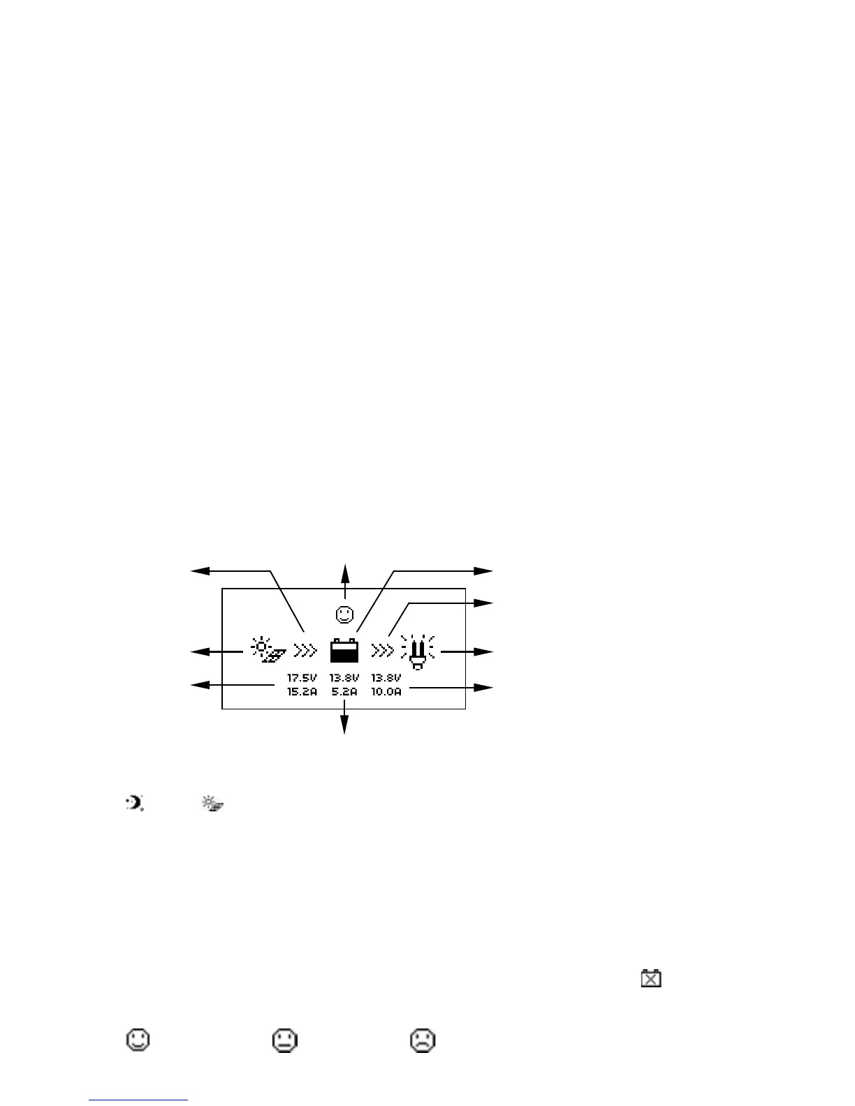
Monitoring screen
Day and night icons
Night, Day: The threshold voltage is 1V. Higher than 1V is daytime.
Charge current icon
The icon is dynamically if there is charge current.
Battery icon
The battery capacity is dynamically displayed based on the SOC value calculated
by the contoller.
Note: When the battery is in over discharge status, the icon displayed is“
”.
Battery status icons
Normal voltage, Under voltage, Over discharge.
Day and
night icons
PV vol. and
cur. values