ProMinent
®
Page 14
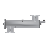
Controller
4.3.6 Sensor Signal System
The UVC sensor monitors UVC output.
A drop in the sensor signal can be caused by:
• the formation of a coating on the lamp’s protective tube
•a considerable deterioration in the UV transmission of the water
•a reduction in the UVC output of the lamp due to ageing.
The operator can choose between a relative display of the sensor signal in % or an absolute
display in W/m
2
.
NOTE
The sensor signal display will not be correct until calibration has been carried out. It is
displayed in % as standard. Please refer to the separate operating instructions for
special applications that require the sensor signal to be displayed in W/m
2
.
Default setting %
4.3.7 Sensor Calibration
The sensor must be calibrated before the system is commissioned for the first time and every
time the lamp is replaced. It is always calibrated with new lamps that are operated at full
capacity (please refer to the sections entitled “Replacing the Lamp” and “Commissioning”).
NOTE
The sensor can only be calibrated when the system is running. If the sensor signal is too
weak to ensure correct calibration, a flashing double arrow will replace the sensor signal
display in % or W/m
2
and calibration will not be possible.
The warning and safety thresholds are not monitored during calibration.
DANGER
A sensor that has not been calibrated correctly cannot function properly.
This may result in the consumer obtaining water that has not been disinfected adequately.
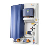
4.3.8 Setting the safety threshold in operating mode “control off”
If the UVC output falls so low that the sensor signal falls below the safety threshold, reliable
disinfection can no longer be ensured. Should this be the case, the stop valve, if there is one,
will close. Two flashing arrows on the display indicate that the signal has fallen below the safety
threshold.
An indicator can be connected to the SAFETY THRESHOLD relay of the control system. The
relay closes when the signal falls below the safety threshold.
Default setting The safety threshold is normally set at 50 % but it can be changed for special applications.
Sensor signal
display
in: %
108 %
Cal.-Factor =
0.420
Time 5:00
50 %
Safety
threshold