6 Assembly
Compare the dimensions on the dimension sheet with
those of the pump.
WARNING!
Danger of electric shock
If water or other electrically conducting liquids penetrate
into the drive housing, in any other manner than via the
pump's suction connection, an electric shock may occur.
– Position the pump so that it cannot be flooded.
WARNING!
The pump can break through the base or slide off it
– Ensure that the base is horizontal, flat and perma‐
nently load-bearing.
Capacity too low
Vibrations can disturb the liquid end valves.
–
Do not allow the base to vibrate.
CAUTION!
Danger from incorrectly operated or inadequately main‐
tained pumps
Danger can arise from a poorly accessible pump due to
incorrect operation and poor maintenance.
– Ensure that the pump is accessible at all times.
–
Adhere to the maintenance intervals.
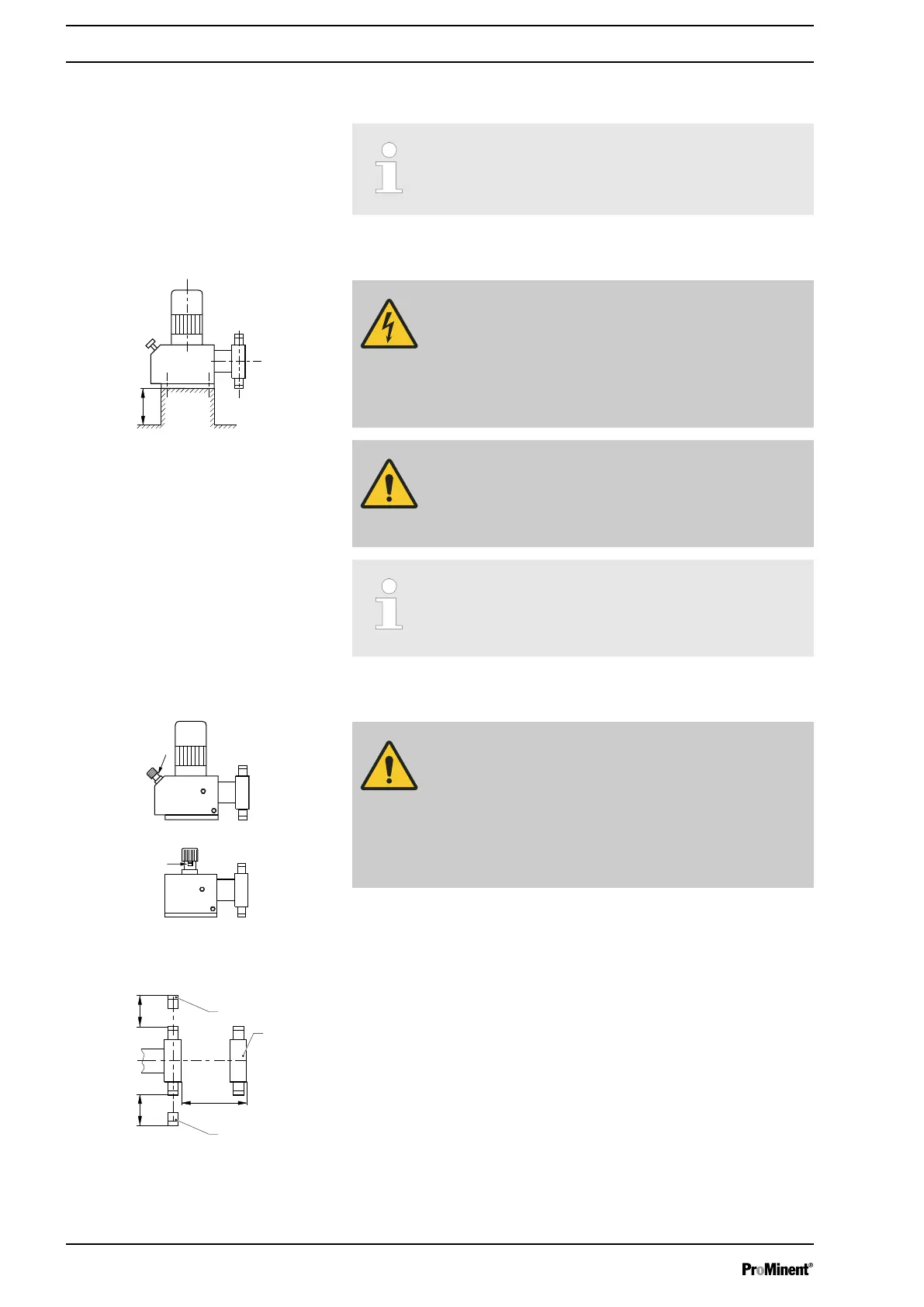
Position the pump so that control elements such as the stroke length
adjustment knob or the indicating dial A are easily accessible.
If the HMI is mounted remotely from the pump: a clearly marked Stop
mechanism must be installed in the direct vicinity of the pump for emer‐
gencies!
1 Discharge valve
2 Dosing head
3 Suction valve
Ensure there is sufficient free space (f) around the dosing head as well as
the suction and discharge valve so that maintenance and repair work can
be carried out on these components.
Base
Fig. 12
Space requirement
Fig. 13
Fig. 14
Assembly
24

 Loading...


