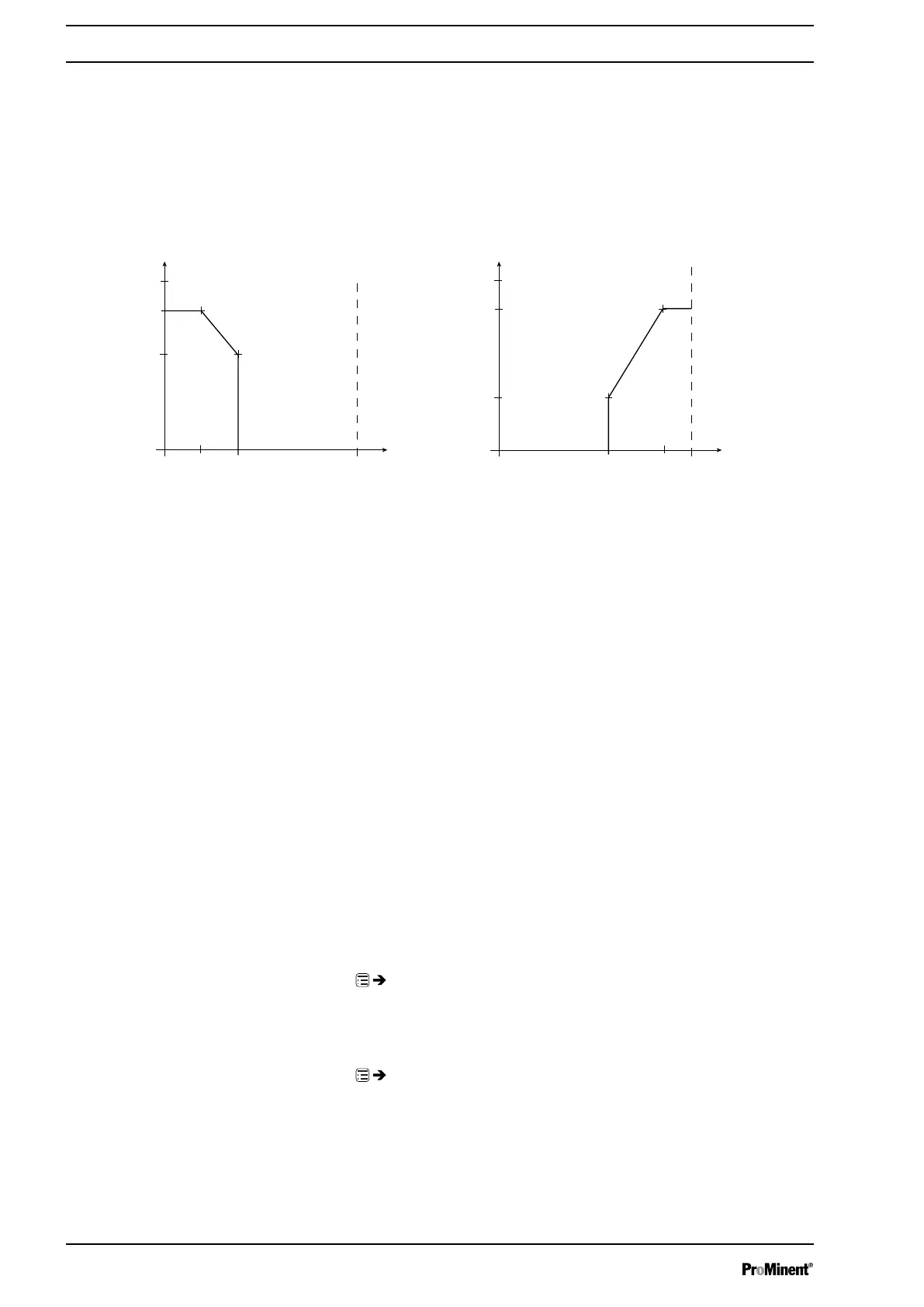
Using this type of processing, you can control a metering pump using the
current signal as shown in the diagram below. You can enter the curve
points I and F in the
‘Curve points’
menu.
However, you can also control two metering pumps for different feed
chemicals via a current signal (e.g. one acid pump and one alkali pump
using the signal of a pH sensor). To do this, connect the pumps electrically
in series.
I [mA]
I 1 I 2
F2
F1
0 20
a) b)
P1
P2
Fmax
B0089
I [mA]
I 1
I 2
F1
0 20
P1
P2
F2
Fmax
Fig. 33: Frequency-current diagram for a) Lower side band, b) Upper side band
‘Upper side band’
Using this processing type, you can control a metering pump using the
current signal as shown in the diagram above. You can enter the curve
points I and F in the
‘Curve points’
menu.
Everything functions according to the
‘Lower side band’
type of the pro‐
cessing.
Curve points
To define the above curves, enter any two points P1 (I1, F1) and P2 (I2,
F2) in the
‘Curve points’
menu (F1 is the stroke rate at which the pump is
to operate at current I1, F2 is the stroke rate at which the pump is to
operate at current I2...).
Error mess. i < 4 mA
You can select in the
‘Error message i < 4 mA’
menu item whether the
pump should issue an error message and stop with current signals below
3.8 mA (Standard).
9.3.2
‘Metering’
‘Menu / Information
è
Settings
è
Metering
è
...’
9.3.2.1
‘Metering profile’
‘Menu / Information
è
Settings
è
Metering
è
Metering profile
è
...’
Under
‘Metering
è
Metering profile’
you can precisely match the pump
metering flow over time against the requirements of the particular applica‐
tion - see "Functional description” chapter.
Set up /
‘Menu’
50

 Loading...


