CAUTION!
Warning of leaks
Leaks can occur on the pump connection depending on
the insert used.
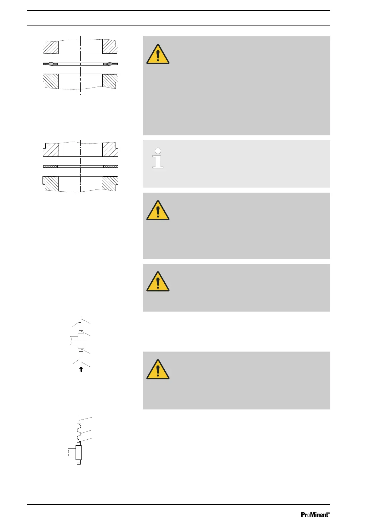
– The pump is supplied with PTFE moulded compo‐
site seals with a flare, which are used for the pump
connectors, which seal the connectors between
grooved pump valves and ProMinent grooved
inserts - see
Ä Further information on page 26
.
– Use an elastomer flat seal in the event that an
unflared insert is used (e.g. third party part) - see
Ä Further information on page 26
.
–
Precise metering is only possible when the back
pressure is maintained above 1 bar at all times.
–
If metering at atmospheric pressure, a back pres‐
sure valve should be used to create a back pressure
of approx. 1.5 bar.
CAUTION!
Warning of backflow
A back pressure valve, a spring-loaded injection valve, a
relief valve, a foot valve or a liquid end do not represent
absolutely leak-tight closing elements.
– Use a shut-off valve, a solenoid valve or a vacuum
breaker for this purpose.
CAUTION!
To check the pressure conditions in the piping system it
is recommended that connecting options for a manom‐
eter are provided close to the suction and pressure con‐
nector.
1 Manometer socket
2 Discharge line (pipe)
3 Discharge valve
4 Suction valve
5 Suction line (pipe)
CAUTION!
Connect the pipelines to the pump so that no residual
forces act on the pump, e.g. due to the offsetting, weight
or expansion of the line.
Only connect steel or stainless steel piping via a flexible
piping section to a plastic liquid end.
1 Steel piping
2 Flexible pipe section
3 Plastic liquid end
Fig. 16: Moulded composite seals with
corrugated insert
Fig. 17: Elastomer flat seal for a smooth
insert
Fig. 18: Manometer connector options
Fig. 19: Steel pipeline at the liquid end
Installation
28

 Loading...


