PRO-VISION® Video Systems
23 provisionusa.com
14. Route and install the extension cable(s) to the cameras final mounting location and connect it to
the camera. Leave enough slack to allow removal of the camera if necessary for service in the
future. (Typically 4-6”)
15. Power on the DVR unit and connect to the Wi-Fi to view the live camera image to properly aim it
on the view page. (See Viewing Cameras on a Smart Device for connection details)
16. After the camera is aimed, tighten the six (6) mounting screws on the sides of the camera.
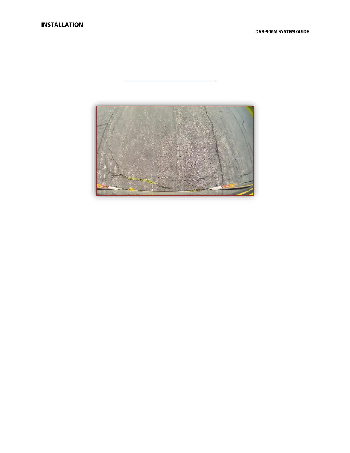
Example view from the rear of a Thomas C2 School Bus