PRO-VISION® Video Systems
42 provisionusa.com
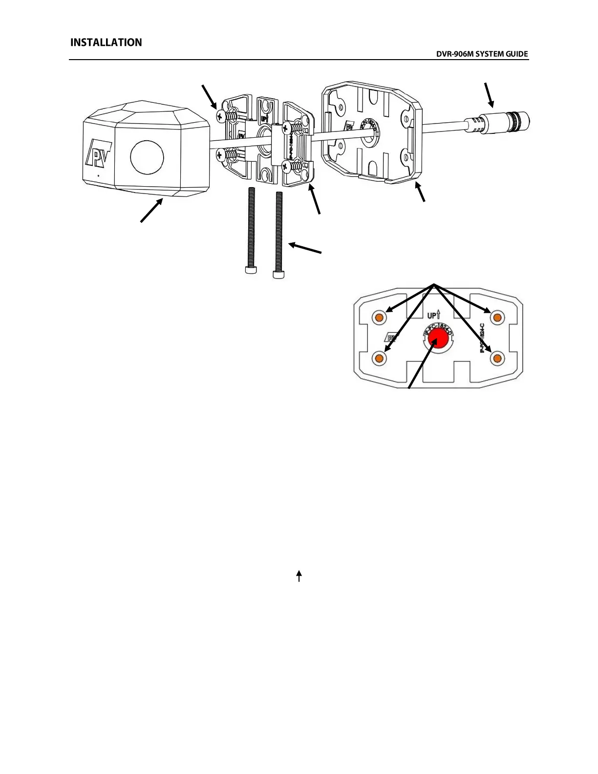
Installation:
1. Attach the camera mounting base to the rubber
mounting gasket as shown to the right. Hold the
mounting base assembly to the desired mounting
location and ensure the base is parallel to the body
lines on the side of the bus. Mark the center of the four
(4) camera base mounting screw locations (shown in
ORANGE) and the large center cable hole (shown in
RED).
2. Place the camera mounting base assembly aside and then verify that there is clearance behind
the four (4) marked mounting screw locations, as well as clearance and access to behind the one
(1) large marked cable hole location.
3. Drill a 1/2” diameter hole in the center marked location (shown in RED above). DO NOT DRILL
THE OTHER HOLES.
4. Using the female end of the camera connection or extension cable, verify there is enough
clearance for the connector to fit through the hole and route toward the recording unit. If needed,
drill the 1/2" hole out to 3/4" to allow the connector to route into the vehicle body.
5. If certain of the camera’s mounting location and that the correct hole for the cable has been
drilled, place the mounting base assembly so that the four (4) ORANGE marks completed in Step
1 are showing. Orient the mounting base assembly so that the bolt cutouts in the base and
gasket point toward the ground and the “UP “ points toward the roof of the bus. Use the four (4)
self-drilling screws provided to attach the base and gasket to the side of the bus.