7 Controller functions
7.1 General controller functions
The controller compares the temperatures of the various measuring points and
charges the storage tank optimally. If the collector temperature exceeds the
storage tank temperature, the solar circuit pump is switched on. Monitoring and
protective functions ensure safe system operation.
7.1.1 RPM control
The A1 output can be operated using RPM control.
For the following control types
230 V block modulation ■
Analogue signal ■
PWM signal ■
the value set limits the minimum control value.
The minimum pump RPM can be congured in a range between 30% and 100%. If
a value of 100% is set, then RPM control is switched o.
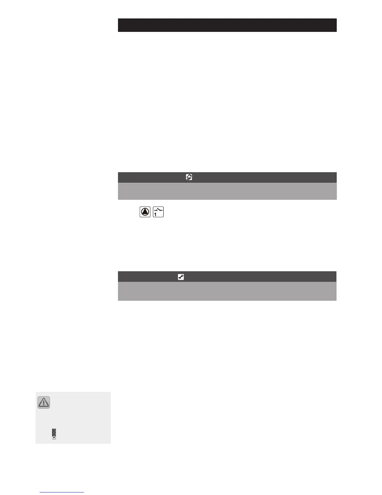
"Programming" menu
Display Meaning Value range Typical set-
ting
min
100
Set minimum pump capacity
using RPM control
100% = RPM control o
30% – 100% 100%
7.1.1.1 Standard 230 V AC pumps
230 V block modulation
Solar circuit pump (switched output A1) is RPM-controlled.
"Basic Setup" menu
Display Meaning Value range Factory set-
ting
Line Value
5 0 Type of pump control
0 = A1 RPM-control-
led – 230 V block
modulation
1
7.1.1.2 HE pumps
The temperature dierence controller in the solar circuit controls the solar pump
RPM in a range between 30% and 100%.
The minimum pump RPM can be congured in a range between 30% and 100%.
If a value of 100% is set, then RPM control is switched o. The pump RPM given by
the controller is indicated as "nSoll" in the curves shown overleaf.
Control of the solar circuit pump via analogue signal
Type A
Pump performance is controlled via a 0 to 10 V analogue signal at O1 (jumper
position ANA)
Output voltage denitions:
Pump o: 0.5 < U < 1.0
RPM control, linear curve 3 <= U <= 10 with minimum pump capacity set to 30%
Selections are made via
the jumper on the connec-
tion assembly.
ANA position: