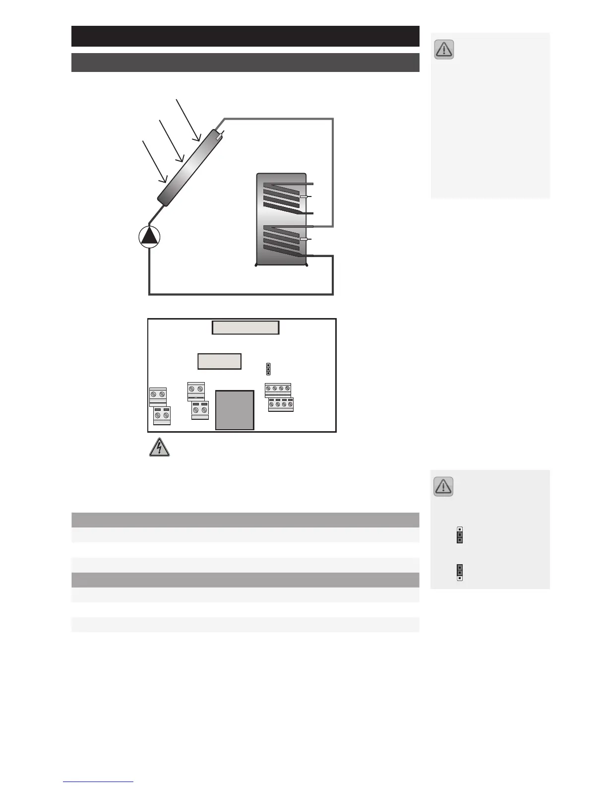
230 V connections
L Mains phase
N Neutral conductor – mains and outputs
A1 Solar circuit pump supply voltage
Sensor connections
S1 Collector sensor
S2 Lower storage tank
S3 General temp. measuring point
O1 Small-signal output for pump control. PWM or analogue (jumper setting)
Operational safety for the
controller/system is only
guaranteed if these are used for
the intended purpose and if no
wiring errors have been made.
Failure to follow the connection
diagrams and safety instruc-
tions can endanger the pump/
system and human life. The
pump manufacturer's instruc-
tions and safety advice must
also be followed.
Selections are made via
the jumper on the connec-
tion assembly.
PWM position:
ANA position: