3.3 Connections
Bear in mind the following points concerning the 230 V connections:
■
If the controller is wired directly into the mains, it must be possible to isolate
mains power by using a switch external to the controller.
The switch is not required if the main power supply is provided via a cable and
earthed mains plug.
The controllers are designed for use with 230 V/50 Hz mains power. Any pumps ■
to be connected must also be rated for use at this voltage!
All earth leads must be attached to the terminals marked "PE". ■
■ The neutral lead terminals (N) are connected electrically and are not switched!
The A1 output serves to supply the pump with 230 V AC. Function selection ■
is carried out using the terminal O1 and corresponding jumper setting: "ANA"
(analogue output) or "PWM" (PWM output). For pumps with analogue signal
control via a 0-10 V analogue signal and pumps with PWM control via a PWM
signal at a freq. of 2 kHz.
3.4 Temperature sensor connection
SOLAREG II BASIC HE devices use PT1000 precision platinum temperature sensors.
2 sensors are required, the third sensor is optional.
Mounting / wiring the temperature sensors:
■ Mount the sensors on the collector and storage tank. Ensure proper heat
transfer, using heat-conductive paste if necessary.
Cross-sections for cable extensions (shielded): ■
- Up to 15 m, 2 x 0.5 mm
2
- Up to 50 m, 2 x 0.75 mm
2
The shield is connected to earth (PE).
Temperature sensors are connected according to the system layout. You do ■
not need to observe polarity for the two wires when cabling temperature
sensors.
■ Sensor cables must be laid separately from 230 V wires.
Sensor collection boxes equipped with surge protection should be used for ■
collector sensors and cable extensions.
4
Short descriptions and device operation
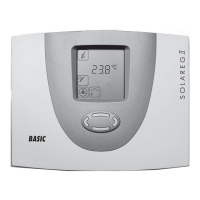
4.1 Display layout
During actual operation, only a selection of these symbols will be shown – de-
pending on the current menu.
Currently active menu ◂
Current display assignment ◂
Current readings, times or controller ◂
states: here 59.6 °C.
Measuring point ◂
Controller state/messages ◂
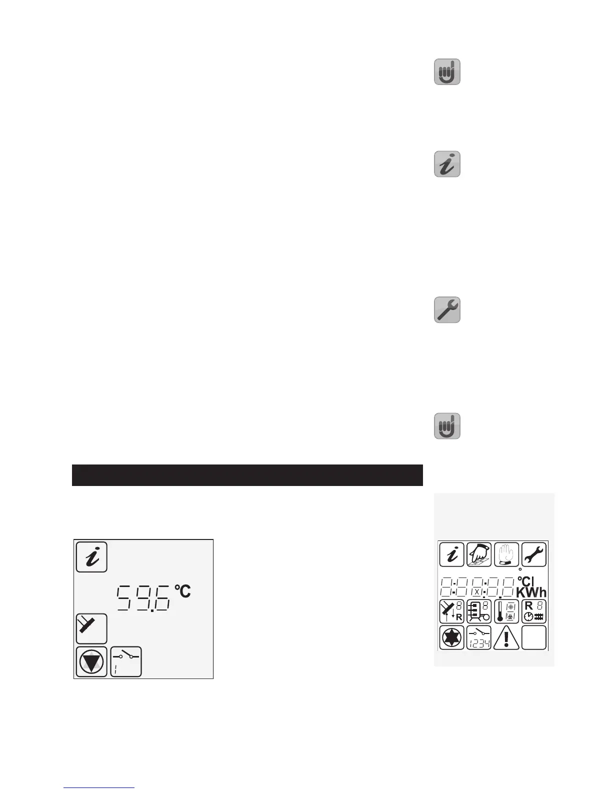
Display symbols
All possible display symbols are
shown below.