PS Engineering
PMA7000B Series Audio Selector Panel and Intercom System
Installation and Operator’s Manual
200-780-0004 Page 2-6 Feb. 2004
2.4.12 PA Mute (J1, Pin 18)
Pin 18 of J1 is a TTL logic output that is pulled low during PTT operation. This serves as an input to exter-
nal public address system to prevent feedback during transmissions.
2.4.13 Public Address Function (J2, Pin 18)
By connecting the top connector (J2), Pin 18 to ground, the pilot’s microphone audio is placed on the cabin
speaker output. When the pilot’s PTT is activated, his voice is heard over the speaker. The copilot can con-
tinue to use the selected com.
We recommend installing a toggle switch to connect the cabin speaker output (pin W, bottom connector) to
a rear or public address speaker instead of the cockpit speaker close to the pilot. This will prevent feed-
back.
2.4.14 Control Output (J2, Pin A)
Pin A of the top connector is pulled to ground whenever the AUX button is depressed. This serves as a
control line for external devices, such as a entertainment system that the pilot wishes to control.
This could be used in conjunction with a PA to control J2, Pin 18, as well as an external relay to change to
the cabin speaker from the cockpit.
This pin can also be used to control passenger Karaoke Mode, by connecting to pin V of the J2, or as a
copilot hook switch Pin L of J2, or passenger hook switch pin M, J2.
2.4.15 Intercom wiring
The top connector (J2) is for the intercom and additional functions. See Appendix for intercom connection
configurations. It is critical to the proper operation of this system to have this connector wiring made in
accordance with these diagrams. Use 2- and 3-conductor, MIL-spec cable as shown. Connect the shields at
the audio panel end only, and tie to the audio low inputs as shown.
NOTE: The top connector harness can be custom made by PS Engineering, Inc. Simply call the factory
and obtain a wire harness work-sheet. The harness will be made to your specifications and fully function-
ally tested. All hardware is included.
2.4.15.1 Entertainment Input
The PMA7000B has two INDEPENDENT music inputs. Entertainment input number 1 is J2 pins 15 (left
channel) and 16 (right channel), WRT pin T, and is provided to the pilot and copilot. Entertainment num-
ber 2 is provided to the passengers at all times.
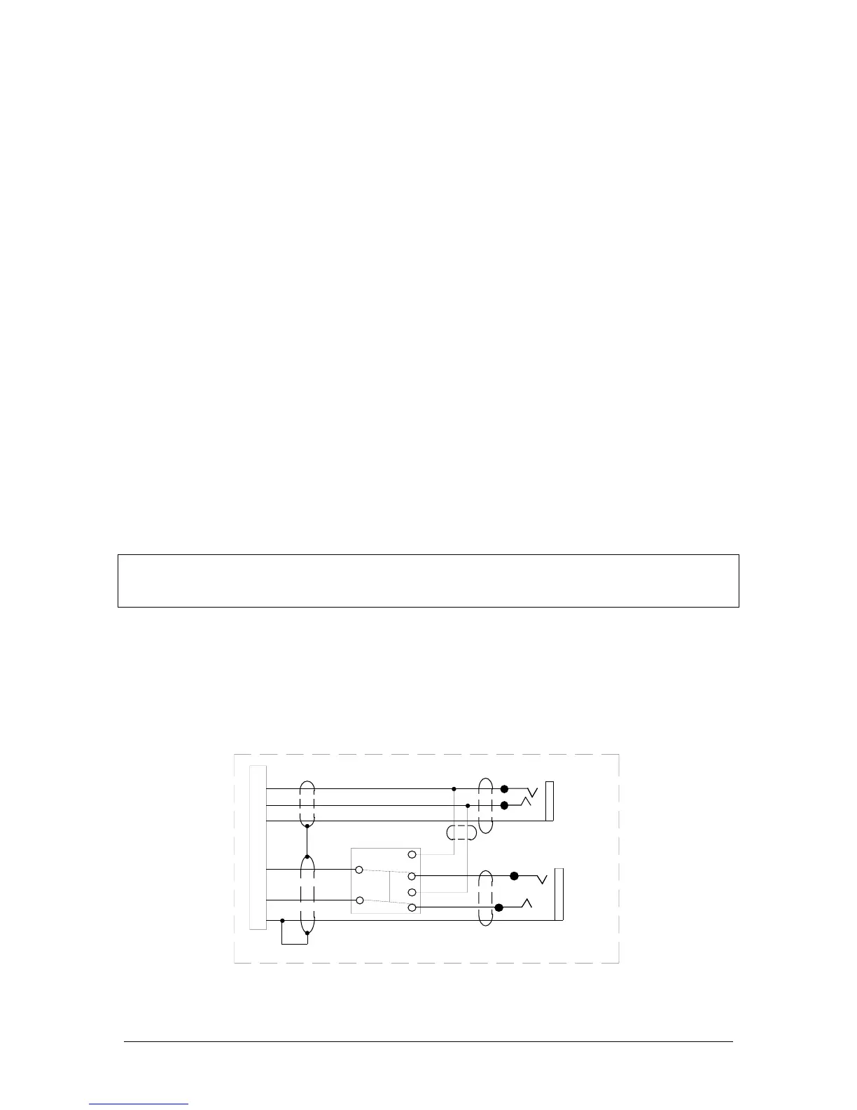
Entertainment 1 and 2 must be connected together in order for all positions to hear the same music source.
We recommend installing a DPDT switch to allow isolation of the music sources if desired.
16
15
T
Ent. #2 Input
14
R
13
Alternate Music Interconnect
Ent. #1 Input