PS Engineering
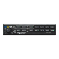
PMA7000B Audio Selector Panel and Intercom System
Installation and Operator’s Manual
200-780-0004 Page 3-2 Feb. 2004
When switching from COM 1 to COM 2 while Com 2 has NOT been selected, Com 1 audio will be switched
off. In essence, switching the mic selector will not effect the selection of Com receiver audio.
When the duplex enable, or TELEPHONE mode is implemented during installation, Com 3 becomes the
“TEL” position. This is the pilot’s “hook” switch, when the system is interfaced to an appropriate approved
wireless telecommunication system, such as the AirCell system. Selecting Com 3 for transmit places the
pilot microphone and headphones on the cellphone. The pilot PTT will switch the pilot mic to the other
selected com transceiver, and allow continued aircraft communications to continue.
The copilot will also be able to transmit on the other selected radio with his PTT as well.
NOTE: Placing the mic selector switch in the COM 3 –TEL– mode will disable pilot and copilot intercom,
as the intercom circuit is transferred to the telephone use. In crew or ISO mode, placing the switch in TEL
mode removes the passengers access to the telephone.
3.3.1 Swap Mode (Switch from Com 1 to Com 2 remotely)
With a yoke mounted, momentary switch, the pilot can change from the current Com transceiver to the
other by depressing this switch. To cancel "Swap Mode," the pilot may either press the yoke mounted
switch again, or select a different Com with the XMT buttons. .
3.4 Audio Selector (All models)
Receiver audio is selected through seven momentary, push-button, backlit switches. You will always
hear
the audio from the transceiver that is selected for transmit.
The users can identify which receivers are selected by noting which of the green switch LEDs are illumi-
nated. Push buttons labeled Nav 1, Nav 2, MKR (Marker), ADF, DME, AUX (auxiliary), and SPR
(Speaker) are "momentary type switches. When one of these buttons is pressed, be active, and the LED will
illuminate. Press the switch again and it be in the "off" position and remove that receiver from the audio.
3.4.1 Speaker Amplifier
The "SPR" in the push-button section stands for speaker. This switch will place all selected audio on the
cockpit speaker when this switch is selected. NOTE: Except for the unswitched audio, the speaker ampli-
fier is not active in the "Split Mode."
Unswitched audio, (autopilot disconnect, altimeter warning, etc.) will come through the speaker regardless
of the speaker button position.
3.4.1.1 Public Address Function
To access PA function, a switch is installed to connect the top connector, pin 18, to ground. This places the
pilot microphone on the speaker output (Pin W) when the PTT is pushed. The copilot can continue to use
the selected com radio.
We recommend that the switch transfer the audio from the cockpit speaker to a cabin speaker for public
address. This will prevent feedback.
3.4.2 Key “Click”
The PMA7000B is equipped with a “click” function that provides an aural feedback to the user in addition
to the tactile button push. This sound can be enabled or disabled by simultaneously holding the COM 1 and
COM 2 buttons in for at least 5 seconds. Any person hearing the radios will also hear the key click.
Allow at least 20 seconds between turning the key click on and off.
3.5 Split Mode
The split mode can be activated at any time by pressing the desired combination of XMT buttons. For in-
stance, to activate a Com 1/Com 2 split, press and hold the Com 1 button, and then press the Com 2 button
while holding the Com 1 button. This places the pilot on Com 1 and the Copilot on Com 2.