PS Engineering
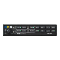
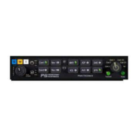
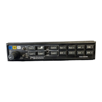
PMA7000B Series Audio Selector Panel and Intercom System
Installation and Operator’s Manual
200-780-0004 Page 2-11 Feb. 2004
2.10 Post Installation Checkout
After wiring is complete, verify power is ONLY on pin 20 of the J1 (bottom connector), and airframe
ground on bottom connector pin Z. Failure to do so will cause serious internal damage and void PS Engi-
neering's warranty.
2.11 Unit Installation
To install the PMA7000B, gently slide the unit into the mounting rack until the hold-down screw is en-
gaged. While applying gentle pressure to the face of the unit, tighten the 3/32" hex-head in the center of the
unit until it is secure. DO NOT OVER TIGHTEN.
Warning: Do not over-tighten the lock down screw while installing the unit in tray.
Internal damage will result.
2.11.1 Operational Checkout
NOTE: The IntelliVox® is designed for ambient noise levels of 80 dB or above. Therefore some clipping
may occur in a quiet cabin, such as without the engine running, in a hangar. This is normal.
1. Apply power to the aircraft and avionics.
2. Plug headsets into the pilot, copilot, and occupied passenger positions.
3. Verify fail-safe operation by receiving and transmitting on com 1 from the pilot position, with the au-
dio panel power off. The Com audio will be present in the right ear cup only.
4. Switch on the unit by pressing the volume (VOL) knob.
5. Check intercom operation.
6. Push the Com 1 Xmt select button (lower row).
7. Verify that both of the Com 1 buttons light. Verify that transmit button LED (Light Emitting Diode)
near the mic selector is not
blinking. If the LED is blinking, stop testing and troubleshoot the micro-
phone PTT installation.
8. Verify proper transmit and receive operation from the copilot position, noting that the copilot PTT
switch allows proper transmission on the selected transceiver. Verify that the Com 1 Xmt button blinks
when transmitting.
9. Verify that pushing the C
OM 2 button causes the button to illuminate, and the Com 2 receiver to be
heard. Verify operation on Com 1 from the pilot position.
10. Repeat for Com 2 and standard Com 3, (if installed).
11. Press and hold the Com 1 Xmt button. While holding the Com 1 button, press the Com 2 Xmt button.
This places the unit in “split Mode;” Verify that the pilot can transmit and receive on Com 1, while the
copilot transmits and receives on Com 2.
12. If the audio panel is installed with J2, pin J grounded, it is configured for duplex operation on Com 3.
Verify that the pilot headset is connected to the cellular telephone system (if installed). Verify that by
using the pilot side PTT, the pilot can transmit on the other selected radio (Com 1 or Com 2). Verify
that the Com 3 Xmt LED blinks at about twice the rate of com 1, to indicate a duplex mode. The copi-
lot has radio transmit capability in Com3 duplex mode, on the selected Com ( 1 or 2). However, he
will have Com 3 capability if the copilot hook switch is grounded.
13. Verify proper operation of all receiver sources by selecting them using the appropriate button. The
button illuminates to show which source is in use.
14. Push the SPR button. Verify that all selected audio is heard in the cockpit speaker. Verify that the au-
dio mutes when the mic is keyed.
15. Verify that the appropriate LED in the lower right side blinks when either push to talk is keyed.
16. Verify proper Intercom system operation in the A
LL, ISO and CREW modes (see Table 3-1).