PS Engineering
PMA7000B Series Audio Selector Panel and Intercom System
Installation and Operator’s Manual
200-780-0004 Page 2-2 Feb. 2004
FHP 6-32 x ½" screws (475-632-0012). The audio selector panel must be supported at front and rear of the
mounting tray.
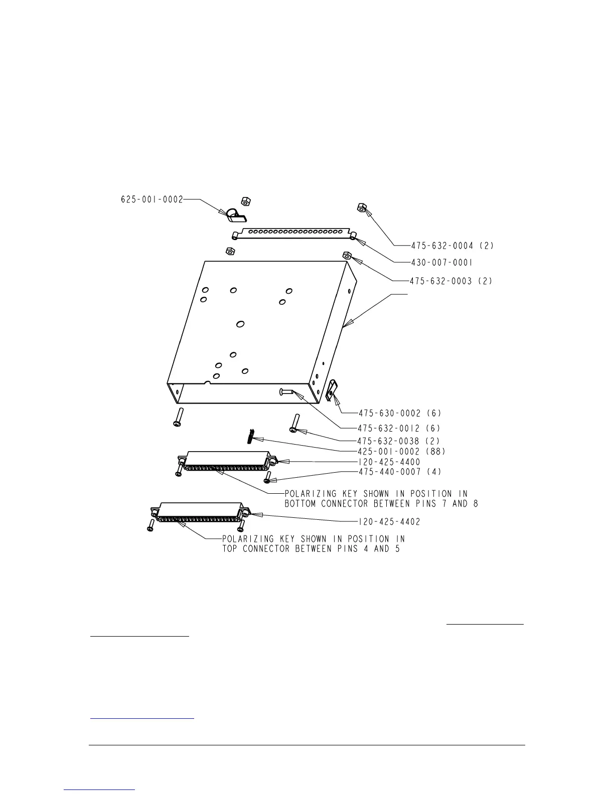
2.3.4 Audio Panel Tray and Connector Assembly
The unit connectors mate directly with the circuit boards in the PMA7000B. The connectors are a Molex
crimp-type, and require the use of a Molex hand crimp tool, EDP P/N 11-01-0203, CR6115B (or equiv.).
The connectors are mounted to the unit tray with #4-40 screws (475-440-0007), from the inside of the tray.
Ensure that proper strain relief and chafing precautions are made during wiring and installation, using the
cable clamp (625-001-0002). Secure the ground bar (430-007-0001), if desired using, #6-32 nuts (475-632-
0003) and #6-32 lock nuts (475-632-0004).
Figure 2-1 Audio Panel Tray Assembly Drawing
2.4 Cable Harness Wiring
Referring to the appropriate Appendix, assemble a wiring harness as required for the installation. All wires
must be MIL-SPEC in accordance with current regulations. Two- and three-conductor shielded wire must
be used where indicated, and be MIL-C-27500 or equivalent specification. Proper stripping, shielding and
soldering technique must be used at all times. It is imperative that correct wire be used.
Refer to FAA Advisory Circular 43.13-2A for more information. Failure to use correct techniques may
result in improper operation, electrical noise or unit failure. Damage caused by improper installation will
void the PS Engineering warranty.
NOTE: PS Engineering can make a custom wiring harness for the intercom. Call 1-800-ICS-AERO or see
www.ps-engineering.com
for details.
120-430-0420