PS Engineering
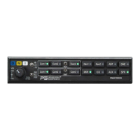
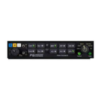
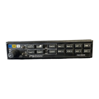
PMA7000B Series Audio Selector Panel and Intercom System
Installation and Operator’s Manual
200-780-0004 Page 2-8 Feb. 2004
Install the “ACK” button in a location convenient to the pilot and copilot position. This switch is a momen-
tary SPST switch between J2 Pin W and ground.
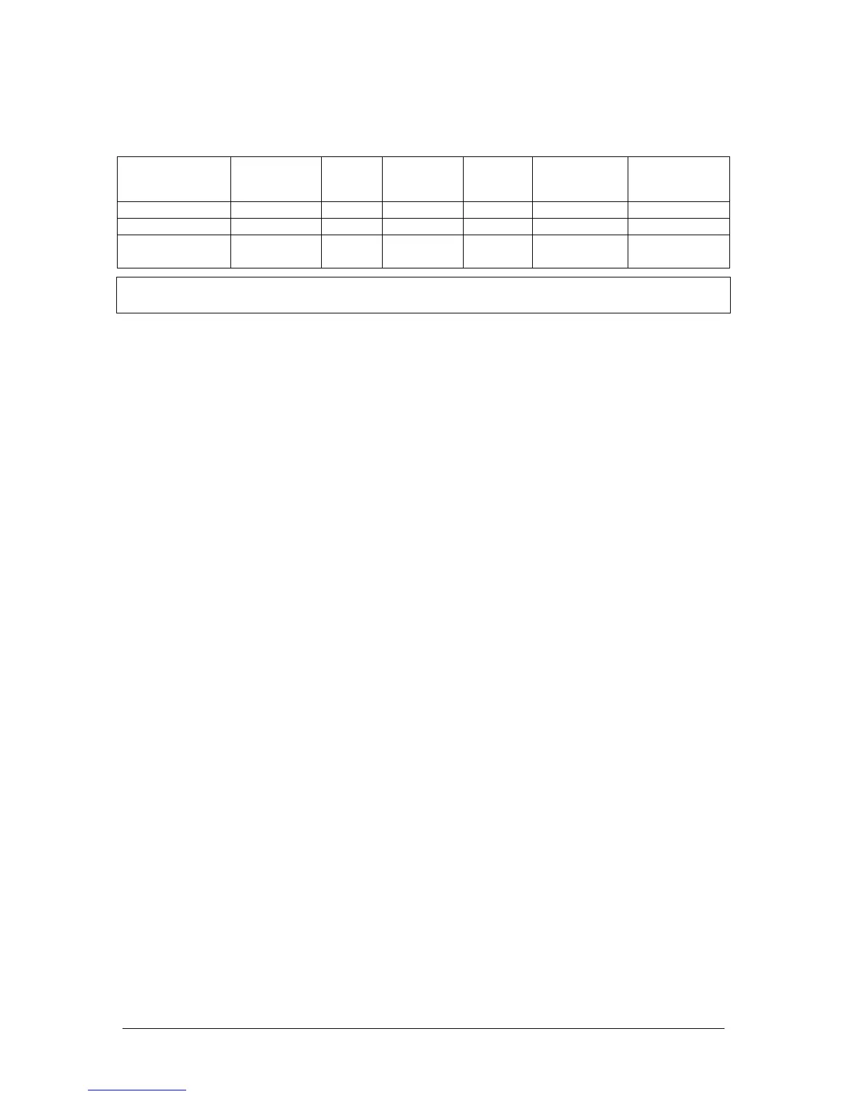
The following table contains information regarding various inputs.
Function EGT or CHT Fuel
Flow or
Level
Oil Pressure
or tempera-
ture
Volt/
Amp
RPM Manifold
Pressure
PMA7000B Pin Z 22 Y 21 X 20
Message Number 1 2 3 4 5 6
Message Text “Check tem-
perature”
“Check
fuel”
“Check
oil”
“Check
battery”
“Check en-
gine speed”
“Check boost”
NOTE: PS Engineering can only provide input information at this time. Approval basis is the responsibility
of the installer. Contact PS Engineering for more information.
2.6 Marker Beacon Installation
The marker beacon receiver is an option included in the PMA7000B. Non-marker (PMA7000) units can
provide audio interface with the external receiver (see section 2.5.4).
2.6.1 Marker Antenna Installation
A marker beacon antenna, appropriate to the type and speed of the aircraft, is required (not included). Re-
fer to aircraft and antenna manufacturer's installation instructions, as well as AC43.13-2A (or later revi-
sion), Chapter 3, for information on proper antenna installation techniques. The marker beacon antenna
must be mounted on the bottom of the aircraft.
2.6.2 External Marker Lights (Marker version)
For installations that require external marker beacon lights, there are three outputs that can drive 12-Volt
lamps only. The external output lamps are driven high (typically +9 VDC ±1.5 VDC unloaded, at MAX
brightness) when active. Maximum source current per lamp is 125 mA. Voltage varies with photocell dim-
ming.
2.6.3 Middle Marker Sense (Marker version)
A Middle Marker Sense output signal is available from the 7000B to flight control systems. This function
will not operate during the test mode. This output will go to +4.5 VDC (± 1.0 VDC) when a valid Middle
Marker signal is received. This output is J1, pin 2.
2.6.4 Marker Audio Input (non-marker version)
If using an external marker receiver, the audio input is J1, pin 21 (MKR input).
2.7 Adjustments
The PMA7000B is factory adjusted to accommodate the typical requirements for most aircraft configura-
tions. There are five adjustments however, that will allow the installer to tailor the specific functions.