PS Engineering
PMA7000B Series Audio Selector Panel and Intercom System
Installation and Operator’s Manual
200-780-0004 Page 2-9 Feb. 2004
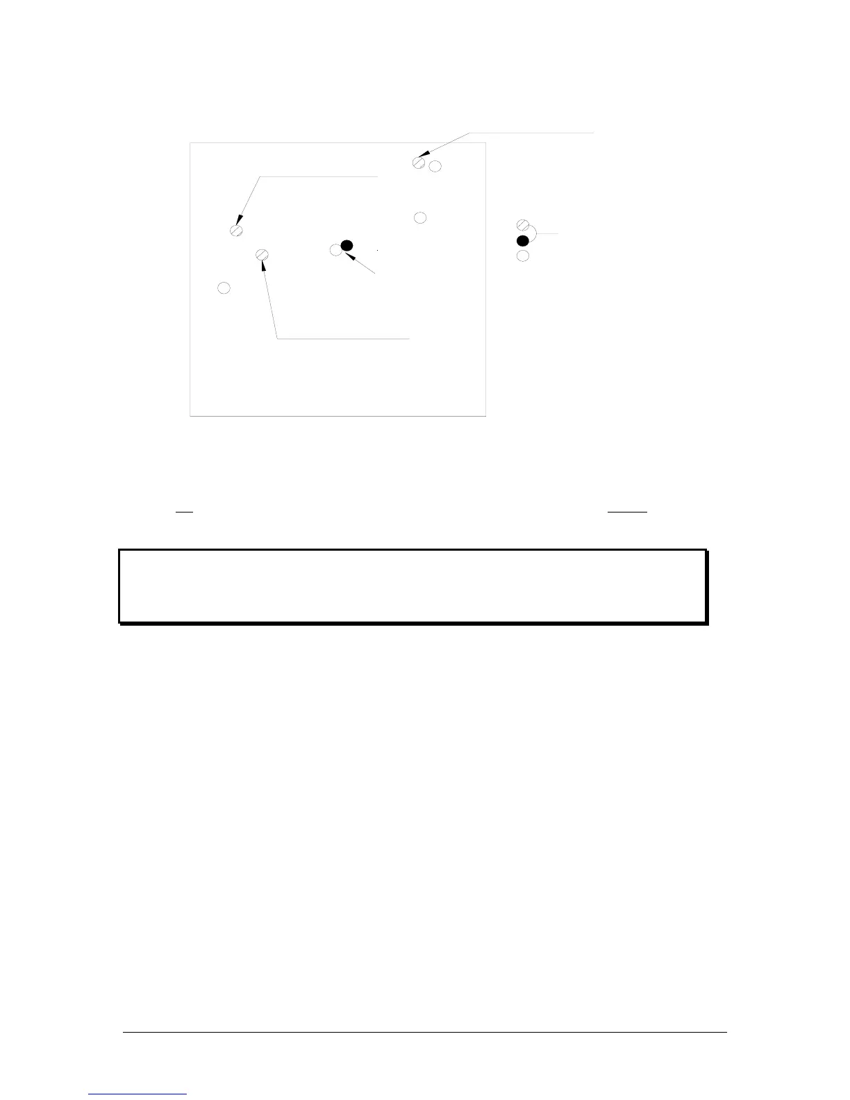
Marker Overall Gain
CW- Reduce
Marker Audio
CW Decrease Volume
MKR Low Sense
CW Decrease Sens.
Front of Unit
PMA7000B adjustment holes
Not used
Speaker Volume
CW-Increase
211
231
223
133
111
Figure 2-3- PMA7000B Adjustments
2.8 Communications Antenna Installation Notes
For best results while in Split Mode, it is recommended that the one VHF communications antenna is lo-
cated on top
of the aircraft while the other communications antenna is installed on the bottom. Any antenna
relocation must be accomplished in accordance with AC 43.13-2A, aircraft manufacturers’ recommenda-
tions and FAA-approved technical data.
Warning:
It is probable that radio interference will occur in the split mode when the frequencies of the two air-
craft radios are adjacent, and/or the antennas are physically close together. PS Engineering makes no
expressed or implied warranties regarding the suitability of the PMA7000B in Split Mode.
2.8.1 Hook Switches
While the Com 3 button acts as the hook switch for the pilot, additional hook switches must be installed to
have full access to the cellphone system. The copilot hook switch is a SPST switch that connects pin L of
J2 on the PMA7000B to ground to place the copilot mic audio on the Com 3 audio in duplex mode for cell
phone operation.
PMA7000B J2, pin M is the passenger hook switch. Install a SPST switch in a location adjacent to each
passenger headset where cellphone use is desired. When pin M is connected to ground through any switch,
the passenger microphones are all on the Com 3/duplex system.
The hook switches are not active or required unless the audio panel is in Com 3 /Duplex mode, with pin J,
J2 grounded.
The wireless communication “tel” system utilizes an intercom loop. Therefore, any time the cellphone is in
use from the pilot or copilot side, pilot and copilot will lose intercom capability. In the ALL mode, when
the passengers’ activate the cell phone, the pilots will have intercom, and continue to hear and transmit
over the avionics normally. However the passengers will not have intercom, because they are on the tele-
phone.
See section 2.4.14 for alternative connection for the hook switches.