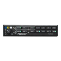
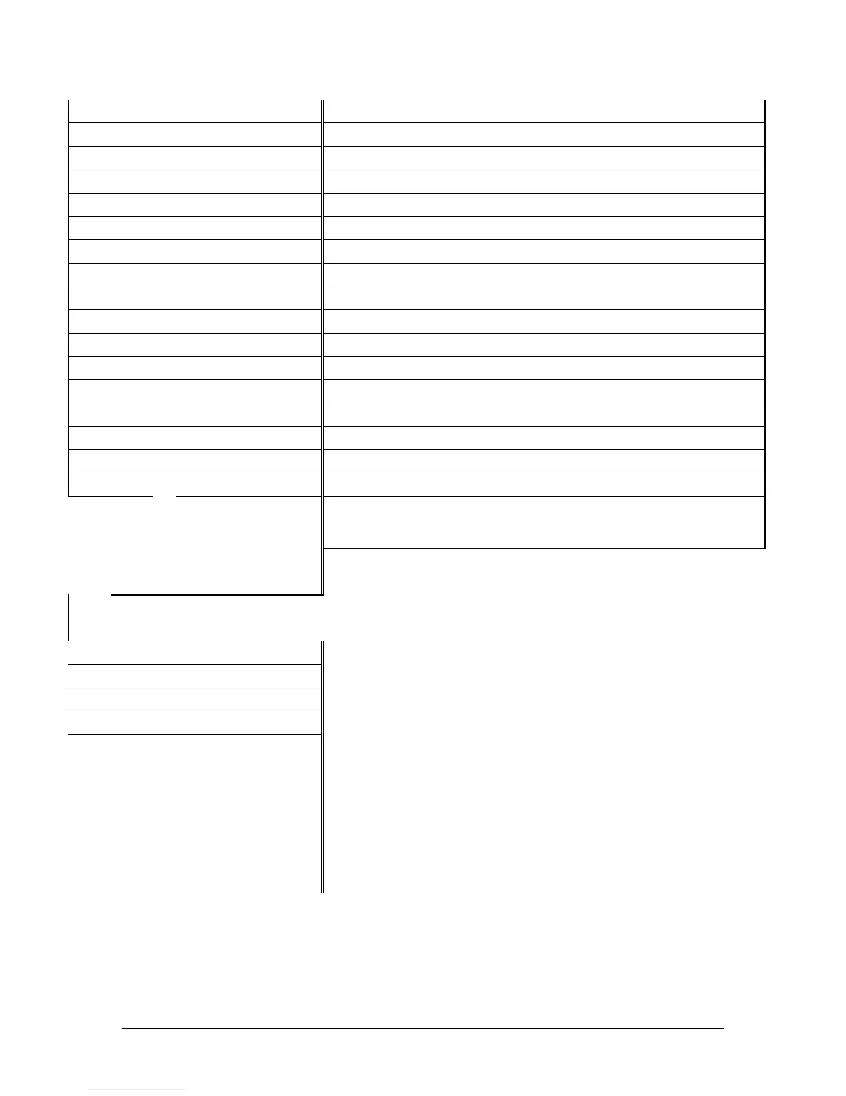
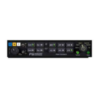
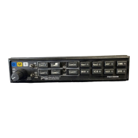
PS Engineering
PMA7000B Audio Selector Panel and Intercom System
Installation and Operator’s Manual
200-780-0004 Appendix G Feb. 2004
P261 Bottom Top
Function
P262 Bottom Top
Function
35 D 14 V Lights 35 13 Music 2 Right Hi
36 J Com 3 Hot Mic Enable 36 N/C Pass ICS Key
37 P Com 1 Mic Audio Hi 37 N/C Pass ICS Key
38 R Com 1 Mic Key 38 6 Pass 3 Mic Aud Hi
39 H Com 2 Mic Audio Hi 39 7 Pass 4 Mic Aud Hi
40 V Com 2 Mic Key 40 N/C Ground
41 K Com 3 Mic Audio Hi 41 11 Pass 3 Phones R Hi
42 15 Com 3 Mic Key 42 11 Pass 4 Phones R Hi
43 19 Com 1 SPR Load Hi 43 N/C Pass ICS Tie
44 L Com 1 SPR Load Lo 44 N/C Pass ICS Tie
45 16 Com 2 SPR Load Hi 45 N/C CVR Audio Out Hi
46 M Com 2 SPR Load Lo 46 N/C CVR Audio Out Lo
47 X Unmuted Audio 4 Hi 47 N/C MKR Audio Out Hi
48 1 Unmuted Audio 4 Lo 48 N/C MKR Audio Out Lo
49 N/C Spare 49 20 MKR SPR Power
50 V Music Mute Enable 50 Z Power Ground
This information is for reference only. PS Engineering, Inc. does not make as-
sertion that the cross reference is accurate or complete for all installations.
Consult the manufacturer’s installation manuals
KMA26
PMA7000B
N/C 1 Pilot Phones Hi (L)
N/C 2 Copilot Phones Hi (L)
N/C 12 Pass Phones Hi (L)
N/C 10 SWAP (Optional)
3 Remove for 14 V lighting
N/C L Copilot Hook Switch (opt)
N/C M Pass Hook Switch (opt)
N/C V Ent. #2 mute inhibit
N/C N/C AirCell Tip
N/C N/C AirCell Ring