DRS4 Evaluation Board User’s Manual
Page 26 of 43
Example of a binary file with two out of four channels being switched on.
3.3. Multi-board configuration
Starting with software version 4.1, multi-board setups are possible. Several evaluation boards
might be connected simultaneously to a computer. On each event, all boards are read out
together, which allows the setup of a small DAQ system with more than four input channels.
The boards can be connected to individual PC USB ports, or an external USB hub can be used.
Please make sure that the USB hub is externally powered, since each board draws 2.5 Watts,
which cannot be satisfied by passive USB hubs. In multi-board configurations, the evaluation
board with the highest serial number becomes the master board, and all other boards are
treated as slave boards with descending serial numbers. Both the trigger and the clock
(reference clock for the DRS4 chip) is passed in a daisy-chain mode from the master board
via the Trigger OUT and Clock OUT connectors to the Trigger IN and Clock IN connectors
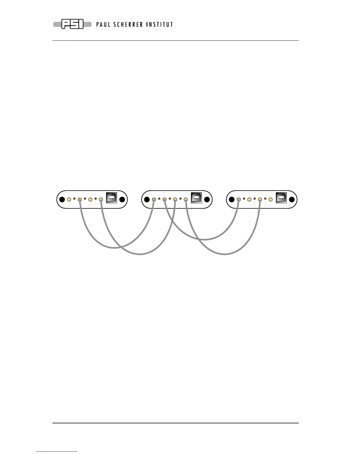
of the first slave board and so on as depicted in the following figure:
In this way, up to 16 boards can be connected. The trigger of the master board can be
configured in the usual way, so it can trigger on an individual channel, a logic combination of
its four channels, or it can trigger on the external input via Trigger IN. The slave boards
receive then the trigger from the master board. A trigger logic incorporating the inputs of the
slave boards however is not possible.
When using multi-board configurations, the maximum event rate is slower than for a single
board, because all boards can only be read out one after the other. So the event rate drops to
about 500 Hz / number of boards. In order to distinguish data from different boards, the board
serial number is written into each event when writing to a XML or binary file (see previous
section).
The timing between boards is poorer than between channels of the same board, which comes
from the fact that the clock distribution causes some jitter when going through two FPGAs. A
typical time resolution between two boards is 60 ps at 5 GSPS when using the clock
distribution, and 400 ps when no clock distribution is used. The additional trigger delay
between two boards is about 16 ns, then means slave board 1 triggers 16 ns after the master
board, slave board 2 32 ns after the master board and so on. When building dedicated DRS4
boards, jitter-cleaner chips and differential clock distribution schemes can be used to keep the
time resolution between boards also below 10 ps.