DRS4 Evaluation Board User’s Manual
Page 27 of 43
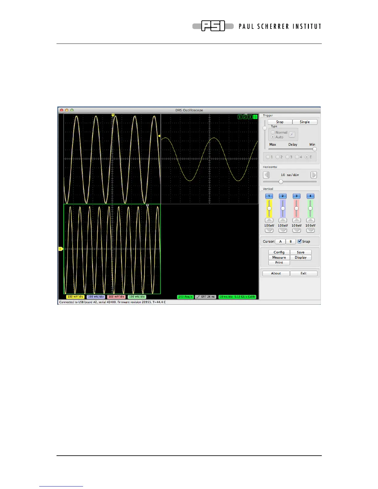
To configure a multi-board system, first connect the boards in the daisy-chain mode as shown
above using MCX cables, and connect the USB cables. Then select “Configure multi-board
daisy-chain” in the “Config” page of the DRSOsc program. The boards will then be
configured correctly (like the trigger and reference clock of all slave boards will be set to
“external”) and read out in sequence. When clicking on the “split-mode display” filed (cross
hair button on the top right corner of the oscilloscope), the waveforms of all connected boards
will be shown simultaneously:
4. Development Hints
The idea behind the evaluation board is to make first steps in using the DRS4 chip, but then
develop your own custom electronics around the chip. The first thing to do there is to study
carefully the DRS4 data sheet, which can be obtained from http://drs.web.psi.ch/datasheets.
Then have a look at the DRS4 Evaluation Board Reference Design, which schematics is
supplied at the end of this document. When you start to design your own electronics, there are
however some important points, which are not necessarily obvious from the data sheet or
from the reference design. These points together with some design tips are explained in this
section.
4.1. Power Supply
As with any analog design, the quality of the power supply is very important, since it has an
influence of the noise level measured by the DRS4 chip. Low noise linear regulators together
with the usual decoupling capacitors are recommended for all power supplies. The analog