PuraTech
®
Owner’s Manual 12/11/2013 25
Assembly and Parts, Cont.
Drive End Cap Assembly Cont.
The Motor is held in place by two 1/2-inch thread-cutting screws. The screws should be “snug.”
The brass pinion gear on the Motor should engage the plastic Drive Gear. The wires should be
securely fastened to the Controller.
The Drive Gear is assembled to the Slide Cam by means of a “keyed” opening, which transfers
the “torque” generated by the Motor to the rest of the drive system. If the drive system becomes
jammed, this opening can become “rounded” causing the gear to turn, but not the Piston Slide
Cam. If this occurs, clear the jam and replace the Drive Gear and Piston Slide Cam.
93219 Piston Slide
Cam Cover
The cover secures the Piston Slide Cam in place and acts as a bushing for the Cam Shaft.
Cam
This is the “heart” of the drive system. A threaded stainless steel shaft runs through the main drive
axle. The Drive Gear is attached at the short end and the Magnet Disk at the other end. The Slide
Cam is assembled inside of the Piston Slide. This Cam Shaft should turn freely before the Motor
Seals the two openings on the Main Control Valve. The larger diameter opening is sealed with an
O-Ring used as an axial or “face” seal. The O-Ring sits in a groove in the End Cap. This groove
must be free of defects such as pits or scratches and also free of debris. The smaller diameter
seal is accomplished with an O-Ring used as a radial seal. The O-Ring should be placed on the
male boss on the End Cap. When assembling the End Cap to the Main Control Valve, care should
be taken to make sure the small O-Ring is aligned with the opening in the Main Control Valve and
that the large O-Ring stays in the groove in the End Cap. If misaligned, the O-Rings can become
The Slide should move freely inside the End Cap Housing.
Assembly
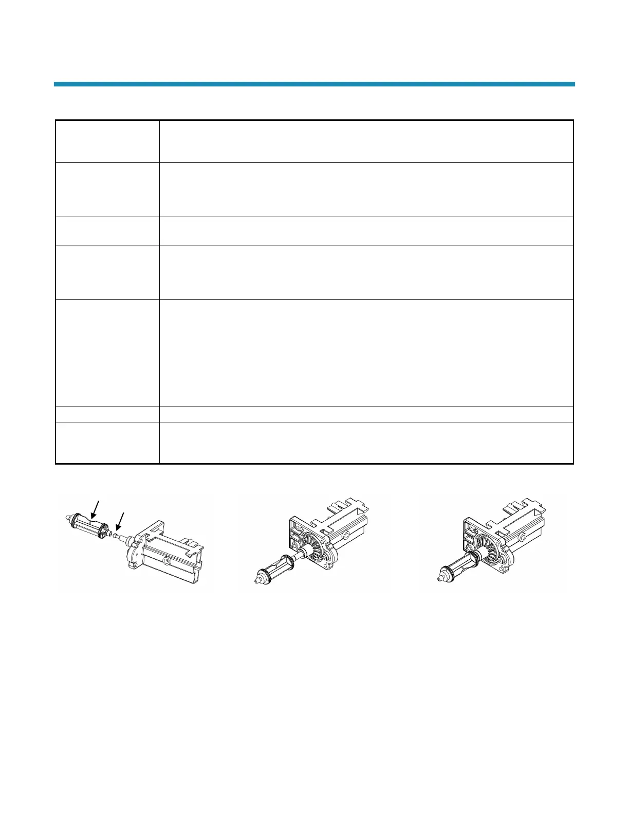
The Drive Piston attaches to the Piston Slide by placing the “slot” of the Piston onto the matching
flat of the Slide. To remove Piston, rotate Piston 90° counterclockwise. To replace Piston, rotate
90° clockwise until you hear an audible “click.” See reference drawings below.
Position Piston Assembly (53322) Vertical
Slide Piston Assembly Onto Piston Slide.
Push Toward End Cap to Stop.
Rotate The Piston Assembly 90 Degrees
Clockwise Until You Hear An Audible Click
As It Snaps Into Place
Align Flats
 Loading...