F1 Input F2 Output F8 Save
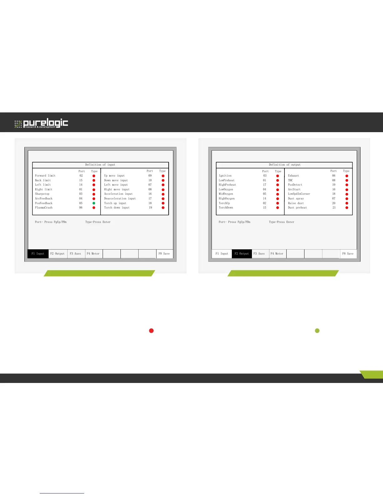
Definition of input
Forward limit 02
Back limit 15
Left limit 14
Right limit 01
Sharpstop 03
ArcFeedback 04
PosFeedback 05
PlasmaCrash 06
Up move input 09
Down move input 10
Left move input 07
Right move input 08
Acceleration input 16
Deacceleration input 17
Torch up input 18
Torch down input 19
F3 Axes F4 Motor
Port Type
Port Type
Port- Press PgUp/PDn Type-Press Enter
F1 Input F2 Output F8 Save
Definition of input
Forward limit 02
Back limit 15
Left limit 14
Right limit 01
Sharpstop 03
ArcFeedback 04
PosFeedback 05
PlasmaCrash 06
Up move input 09
Down move input 10
Left move input 07
Right move input 08
Acceleration input 16
Deacceleration input 17
Torch up input 18
Torch down input 19
F3 Axes F4 Motor
Port Type
Port Type
Port- Press PgUp/PDn Type-Press Enter
Figure 52. Input definition Figure 53. Output definition
Output definition
The controller could change the IO definition, including changing the order of IO number, the type of IO (normally open or closed) according to the user’s
need. In the system custom definition interface, press F3 to enter the definition interface, press F1 to enter the input definition interface.
As shown in fig. 53.
In the interface press [↑], [↓], [←], [→], move the cursor to the position that needs changing, press [PageUp], [PageDown] to change the number of the
Output, press [Enter] to change the type of the Output.
The output type is open drain transistor output type. Type means that if the output signal is effective, the transistor is on. Type means that is
the output signal is effective, the transistor is off.
Coordinate definition
The system could provide IO definition for the user. As shown in Fig. 54.
 Loading...