EasyManua.ls Logo

PUSR USR-DR13 Series - Ethernet Port; LED Indicators

PUSR USR-DR13 Series
46 pages
Print Icon
To Next Page IconTo Next Page
To Previous Page IconTo Previous Page
Loading...
USR-DR13X User Manual
pusr.com
- 6 -
5
GND
P
The digital ground
2.1.3. Ethernet port
USR-DR13X series adopt 10Base-T/100Base-TX adaptive Ethernet RJ45 interface which supports automatic
MDI/MDIX connection.
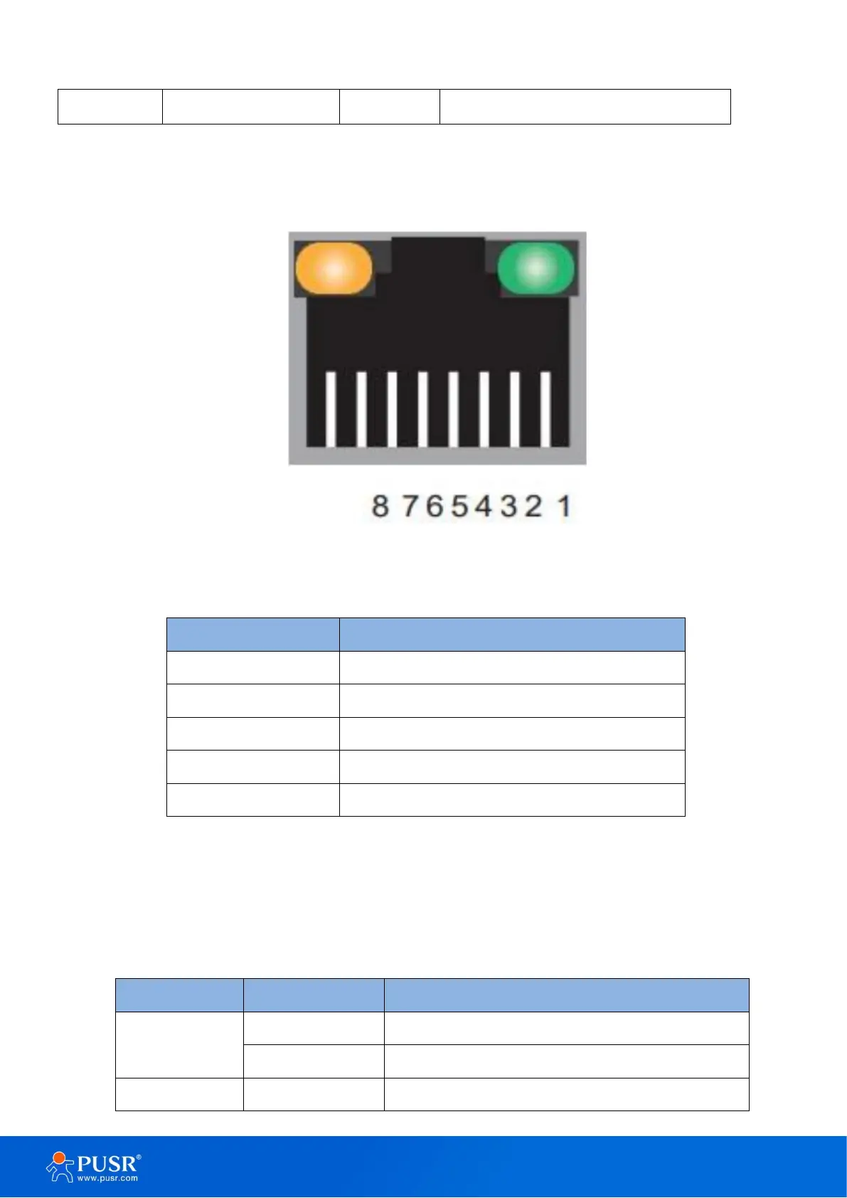
Figure 2. RJ45 with light
Table 3. Ethernet pin assignment
Pin number
Signal name
1
Send data+(TD+)
2
Send data-(TD-)
3
Receive data+(RD+)
6
Receive data-(RD-)
4, 5, 7, 8
Unused
2.1.4. LED indicators
There are 4 indicators on the device: POW, WORK, COM, LINK. The LED indicators description is in the
following table.
Table 4. LED indicators description
LED name
Status
Description
Power(Red)
ON
Power supply is normal
OFF
No power supply or abnormal power supply
Work(Green)
Blinking(Slow)
System is booted up and running