6
The large bracket:
• Has two top screw holes at either end of the large bracket, 16”
(40.6 cm) apart which are designed to match standard stud spacing.
Refer to Figure 3-2.
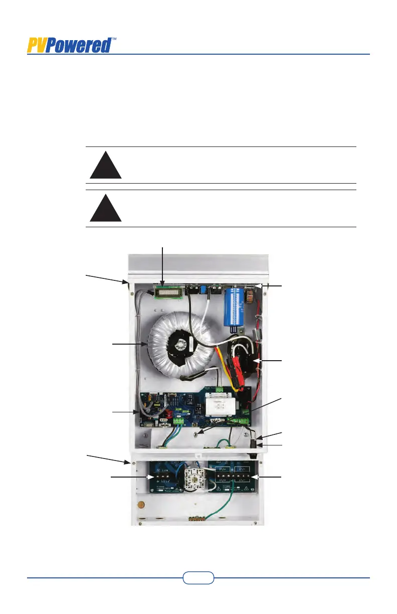
The inverter also has an internal mounting screw. Refer to Figure 2-1 for
the location of this screw.
!
WARNING
Before drilling holes to mount the inverter, verify that there are
no electrical wires or plumbing in the area.
!
AVERTISSEMENT
Avant de percer des trous pour installer l’onduleur, vérier qu’il
n’y a aucun l électrique ou plomberie dans le secteur.
Figure 2-1 Interior Components of the Inverter/Disconnect Unit
Control Board
with LED Lights
Transformer
Inductor
Power Board
Display
GFI Fuse Port
Mounting Screw
Inverter
Disconnect
AC Wiring
Connections
DC Wiring
Connections
GFI Fuse Terminals
 Loading...