7
3.1 Mounting and Anchoring the Inverter and Integrated
AC/DC Disconnect
After you have determined a suitable location for the inverter/disconnect
unit, the next step is anchoring the bracket to the wall stud(s).
Models PVP1100, PVP2000, PVP2500, PVP2800, PVP3000
and PVP3500
1. Locate a wall stud in the desired location and align the mounting
bracket or paper mounting template with the vertical row of screw
holes over it for a single-stud mount. Mark the mounting holes
ensuring holes A through D are directly over the single stud.
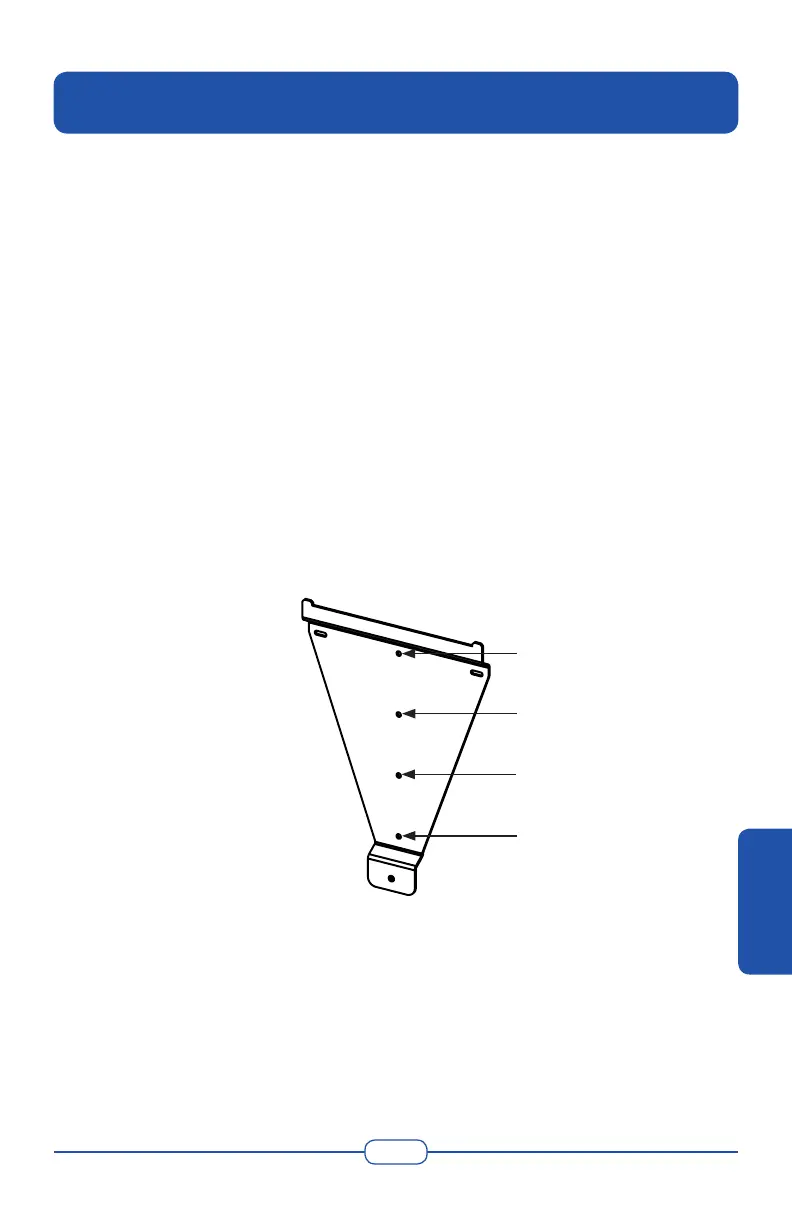
2. VERIFY THE BRACKET IS LEVEL. Align points A through D with
the wall stud. Drill 1/8” (.32 cm) pilot holes for the screws.
• Use heavy-duty 1/4” x 2” (.635 cm x 5 cm) (coarse thread lag
screws to secure points A, B and D.
• Use an 1/8” (.32 cm) screw (and anchor if necessary) to secure
point C. Refer to the following gure.
Figure 3-1 Small Mounting Bracket
3. Carefully hang the inverter/disconnect unit on the upper part of the
bracket. The hooks located at the rear of the inverter should hang over
the bracket.
4. Verify the inverter/disconnect unit is level.
5. Remove the front lid of the inverter by unscrewing the two cover
screws located at the bottom perimeter of the inverter.
A
B
C
D
3. Installation
INSTALLATION