47
B.1 Field Configuration of an Inverter for Use with
Positively Grounded PV Arrays
If the inverter is:
• Equipped with an Integrated AC/DC Disconnect, use the instructions
in “Inverter
with
an Integrated AC/DC Disconnect”.
Otherwise, if the inverter is:
•
Not
equipped with an Integrated AC/DC Disconnect, skip to the sec-
tion titled “Inverter
without
an Integrated AC/DC Disconnect”.
Inverter with an Integrated AC/DC Disconnect
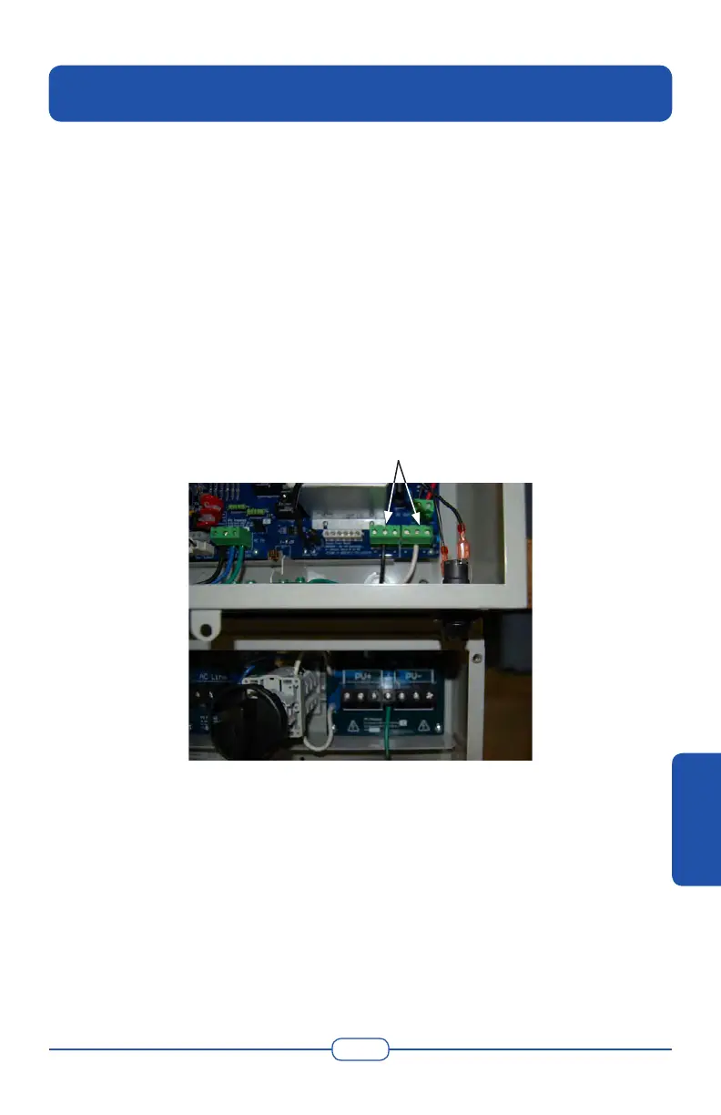
1. Inside the inverter remove both the grounded and ungrounded
conductors from the terminals on the Power Board.
Inverter’s Power Board DC
Terminals
Figure B-1 Inverter’s Power Board Terminals
2. Install the black conductor into the center “+” terminal on the right
side.
3. Install the white conductor into the center “–” terminal on the left
side.
Appendix B - Ground Configuration
APPENDIX B
 Loading...