EasyManuals Logo
Home>Pyle>Car Receiver>PLMRB29B

Pyle PLMRB29B User Manual

Pyle PLMRB29B
15 pages
To Next Page IconTo Next Page
To Previous Page IconTo Previous Page
Page #5 background imageLoading...
Page #5 background image
- 4 -
- Only use speakers with 4 ohms impedance.
- Do not attach the control panel to the chassis before wiring is complete.
- The maximum current of the auto antenna is 200mA.
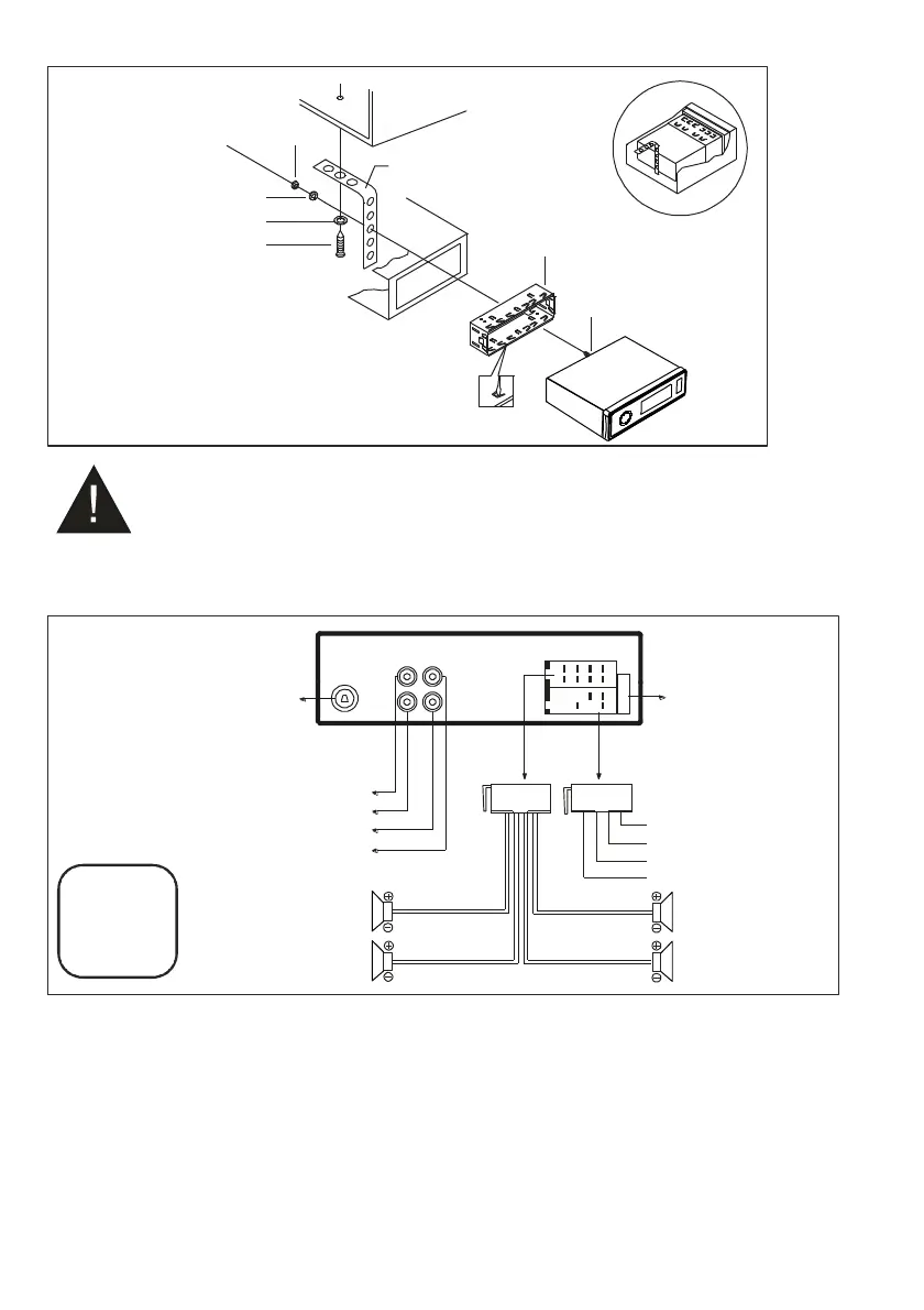
Wiring Connections
WIRING
DIAGRAM
Removal of the Main Unit
1. Remove the metal strap from the main unit.
2. Remove the plastic trim out from the main unit.
3. Insert a bracket key into the left and right side of the main unit and draw the unit out of the mounting
sleeve.
INSTALLATION
DIAGRAM
Rear Left Speaker
Purple / Black
SPRING WASHER
DIAGRAM
PLAIN WASHER
DIAGRAM
TAPPING SCREW
DIAGRAM
HEX NUT
DIAGRA
M
DASH BOARD
DIAGRAM
CONSOLE
DIAGRAM
MOUNTING SLEEVE
DIAGRAM
HEX BOLT
DIAGRAM
Radio Antenna Socket
White: Front Left CH RCA Audio Output
Red: Front Right CH RCA Audio Output
White: Rear Left CH RCA Audio Output
Red: Rear Right CH RCA Audio Output
FUSE 15A
ACC (Red)
GND(Black)
ANT(Blue)
Power B+(Yellow)
Rear Right Speaker
Front Right Speaker
Front Left Speaker
Purple
Gray
Gray / Black
White
White / Black
Green
Green / Black
CAUTION
+12V DC
NEGATIVE
GROUND
10A

Questions and Answers:

Question and Answer IconNeed help?

Do you have a question about the Pyle PLMRB29B and is the answer not in the manual?

Pyle PLMRB29B Specifications

General IconGeneral
BrandPyle
ModelPLMRB29B
CategoryCar Receiver
LanguageEnglish

Related product manuals